Disassembly/Assembly
Top Enclosure
3-17
Removing the Engine Board
The USB/xD Daughtercard is mounted on the Engine Board. The following procedure describes
removing the Engine Board with the USB/xD Daughtercard attached.
1. Following Steps 2–4, disconnect the cables listed in Table 3-5.
2. Disconnect the shielded wire cable from J18.
3. Disconnect the stranded wire cables from J5, J21, and J33.
4. Disconnect the
fl
at ribbon cable from J15.
5. Remove the two screws that secure the USB/xD Daughtercard to the rear panel.
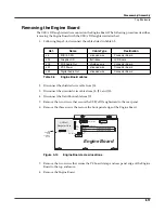
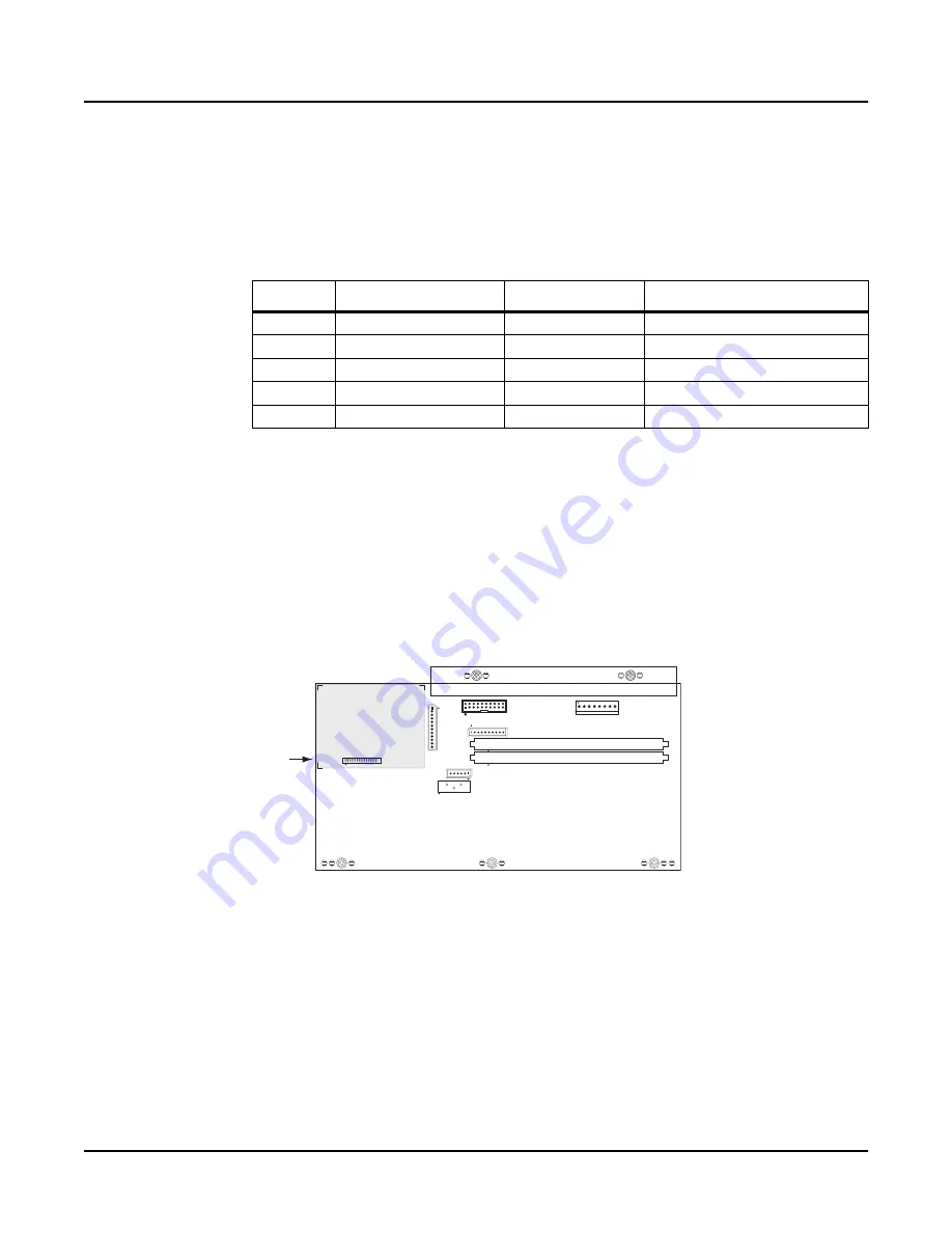
6. Remove the three screws that secure the front panel edge of the Engine Board.
Figure 3-14
Engine Board, screw locations
7. Remove the two screws that secure the PC board clamp and rear panel edge of the Engine
Board to the top enclosure.
8. Remove the Engine Board.
Ref.
Name
Cable Type
Destination
J5
MIDI & CPU
stranded wire
Connector Board
J15
Graphic LCD
fl
at ribbon
LCD Board
J18
PC3 Audio Out
shielded wire
Connector Board
J21
PC3 Power
stranded wire
Connector Board
J33
Digital Audio Out
stranded wire
Connector Board
Table 3-5
Engine Board cables
USB/xD
Daughter Card
J1
PC3 Power
J10
Expansion Sound ROM
J11
J15
J5
J21
J33
Bank 0
Bank 1
Expansion Sound ROM
MIDI & CPU
Dig. Audio Out
J18
Audio
Out
Graphic LCD
J12
USB/SM
Card
on Engine
Board
Battery
J20
Engine Board


