n
Press
RANGE
button to select
between Auto mode & Manual
mode.
n
In Manual mode the range of the
function under test can be
selected.
n
Press
HOLD
once to enter hold
mode.
n
Press
HOLD
again to exit hold
mode.
n
In Hold mode, is displayed and
the present value is shown.
n
Press
Hz/DUTY
once to enter
Duty cycle mode.
n
Press
Hz/DUTY
again to exit
Duty cycle mode.
n
In Hz mode,”
Hz
” is displayed and
in Duty cycle mode “
%
” is shown.
n
Press
SELECT
button to select
between Resistance, Capacitance,
Diode & Continuity test..
H
Buttons
HOLD
(Black Button)
Operation Performed
Hz / Duty
(Black Button)
SELECT
(Black Button)
RANGE
(Black Button)
Functional Buttons
Below table indicates the functional button
operations
10
!
V
W
CAP
NPN
PNP °C
m
A
mA
10A
CE
OFF
OFF
Hz
~
SELECT
RANGE
HOLD
Hz/DUTY
hFE
FUSED
10A/15SEC.
MAX
400mA
1000V MAX
V
W
mA
COM
10A
207 MK-1(T)
399.9
E
E B C
!
~
~
~
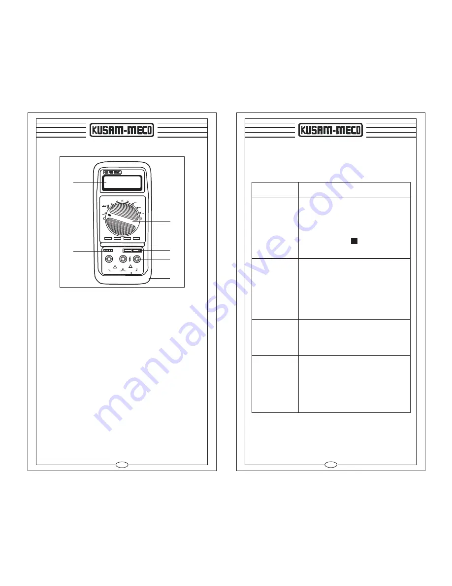
The Multimeter Structure
(see figure 1)
( Figure 1)
1) LCD DISPLAY :
A 3 digit display (maximum reading 3999)
indicates measured values, and features symbols
indicating function, Low Battery,Continuity, Diode.
2)
FUNCTION SELECTOR :
To Select ACV, DCV, ACA, DCA, Resistance,
Capacitance, Temperature, Frequency, Diode,
Continuity & Transistor Test.
3)
Test leads are inserted into these jacks for
Voltage, Resistance, Current measurements,
Continuity & Diode Checks.
4) INPUT SOCKET FOR CAPACITANCE
MEASUREMENT :
Capacitors whose capacitance value is to be
measured are inserted in this jacks.
5)
INPUT SOCKET FOR TRANSISTOR TEST.
6) PROTECTIVE HOLSTER :
Prevents the instrument from damage.
¾
W
INPUT JACKS (V
m
A
,
A
and COM) :
1
2
4
3
6
5
9


