background image

1. Mount all components in a suitable location, preferably in a high area above the air system.      

Do not mount in engine compartment or near any source of heat or dirt.  The system may be 

connected to any point in the vehicle's air system. 

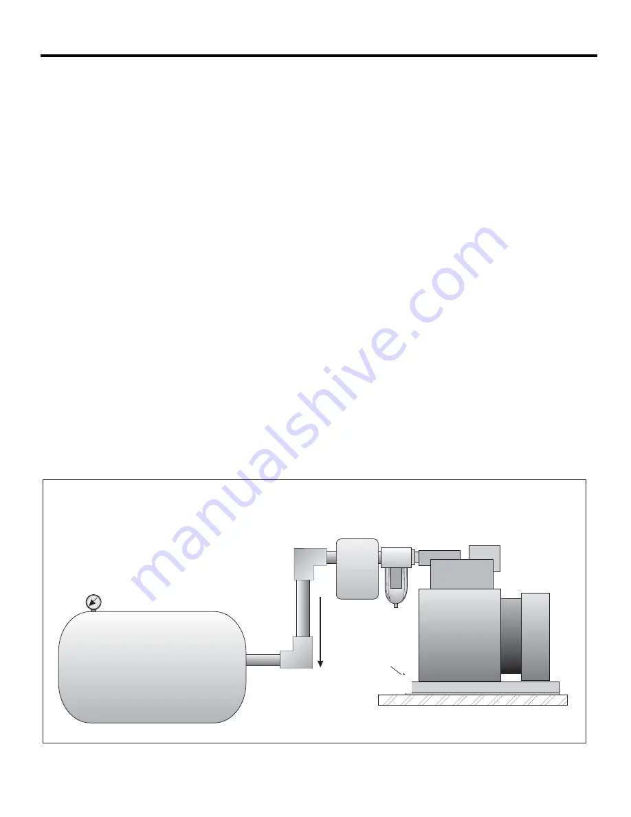
2. Mount air compressor in the position as shown being certain that the compressor is above air 

pressure tank. 

3. CAUTION: 

No condensate or water must be allowed to enter or accumulate in the output of the 

Auto Pump.  Route output pressure line downward from Auto Pump to permit moisture to drain 

away. 

Water in the pump outlet will induce failure.


4. All connections for air lines are 1/4" NPT.  Use Teflon tape, or equivalent on all connections to 

insure no leakage of air. 

5. The recommended installation of the Auto Pump air compressor system is shown below. 

6. Note that an external check valve is located between the compressor and the pressure switch. 

No additional check valve is required. 

7. Mount the air compressor.  Connect a suitable piece of flexible tubing from the outlet port of com-

pressor to the air tank. (Tubing and connectors are not supplied) 

8. An optional Mounting Plate is available to help reduce vibration and noise from Auto Pump and 

to simplify pump mounting.

Auto Pump

091-9B-1

Air Pressure System

Air Line

The Flow of
Any Moisture

1/4" NPT
Outlet Port

Truck
Body

Optional
Mounting
Plate kit
091-9H-1

VEHICLE TUBING INSTALLATION

4

091-09H-1      

Summary of Contents for AUTO-PUMP

Page 1: ...826 sales kussmaul com scan using your mobile device for more information 1YEAR WARRANTY File 091 9B 1_GEN3 Rev A Revised By PS Date 07_06_2016 INPUT 120 volt 50 60 Hz 1 8 AMPS OUTPUT 100 PSI MAXIMUM MODEL 091 9B 1 AUTO PUMP 120 VAC AIR COMPRESSOR SYSTEM INSTRUCTION MANUAL MODEL 091 9B 1 ...

Page 2: ...section eliminating all belts and pulleys assuring long life and reliable operation A heavy duty pressure switch is adjusted to start the compressor when the system pressure drops below 75 psi and stops the compressor when 95 psi is attained The start up pressure is field adjustable the pressure differential between start up and stopping is fixed A moisture trap is mounted on the Auto Pump This he...

Page 3: ...7 5826 sales kussmaul com CAUTION NO CONDENSATE OR WATER MUST BE ALLOWED TO ENTER OR ACCUMULATE IN THE OUTPUT OF THE AUTO PUMP ROUTE OUTPUT PRESSURE LINE DOWNWARD FROM AUTO PUMP TO PERMIT MOISTURE TO DRAIN AWAY WATER IN THE PUMP OUTLET WILL INDUCE FAILURE WATER DAMAGE WILL VOID WARRANTY ...

Page 4: ...ons for air lines are 1 4 NPT Use Teflon tape or equivalent on all connections to insure no leakage of air 5 The recommended installation of the Auto Pump air compressor system is shown below 6 Note that an external check valve is located between the compressor and the pressure switch No additional check valve is required 7 Mount the air compressor Connect a suitable piece of flexible tubing from ...

Page 5: ...ckwise To lower cut in turn range nut counterclockwise Do not exceed 100 PSI cut out COMPRESSOR OUTPUT IS 100 PSI MAXIMUM DO NOT EXCEED 100 PSI OR YOU WILL VOID WARRANTY 120 VOLT A C POWER CORD PRESSURE SWITCH PRESSURE SET POINT ADJUSTMENT TURN CLOCKWISE TO INCREASE BOTH CUT IN AND CUT OUT PRESSURE FACTORY SET TO CUT IN 75 PSI CUT OUT 95 PSI AUTO PUMP 091 9B 1 BLK WHITE WHITE BLK GRN GRN NOTE THIS...

Page 6: ...P Motor Type Shaded pole A C Compressor Output 1 0 1 3 CFM Open Flow 100 PSI Maximum Pressure Switch Adjustable Set Point Factory set to 75 PSI Cut in 95 PSI Cut out Switch Differential 20 PSI Nominal Outlet Connection 1 4 NPT Female 185 77 7 31 3X 88 90 3 50 2X 121 92 4 80 2X 1 75 38 10 1 50 7 08 179 84 2X 150 99 5 94 6X 1 4 20 TAPPED HOLES 195 91 7 71 SPECIFICATION OUTLINE AUTO PUMP ...

Page 7: ...17 64 DIA HOLE 6 PLACES Note Verify measurements before using as a template Must set print settings to Actual Size 4 75 1 75 3 50 TEMPLATE AUTO PUMP 7 ...

Page 8: ...Y 11796 www kussmaul com Ph 800 346 0857 Fax 631 567 5826 sales kussmaul com 8 ACCESSORIES MOUNTING PLATE CAUTION WATER IN THE PUMP OUTLET WILL INDUCE FAILURE WATER DAMAGE OR OPERATING AUTO PUMP OVER 100 PSI WILL VOID WARRANTY 091 9H 1 ...

Page 9: ... charges paid Kussmaul Electronics Company Inc shall have no liability for damages of any kind to associated equipment arising from the installation and or use of the Kuss maul Electronics Company Inc products The purchaser by the acceptance of the equipment assumes all liability for any damages which may result from its installation use or misuse by the purchaser his or its employees or others WA...

Reviews: