background image

Section 2—Specifications


2.2 


Nominal Power 
Requirements: 


   Voltage (VDC)           Current (mA) 

  Without target 
         present: 

 
        13.6                            510 

  With target 
present: 

        13.6                            560 

  Without target & 
         backlight: 

 
        13.6                            520 

  With target &  
         backlight: 

 
        13.6                            570 

  Standby (HOLD):          13.6                            100 


Reverse Voltage 
Protection: 

Diode protection. No damage if 
supply leads reversed. 
 

Electronic 
Components: 

100% solid state; integrated circuits, 
microprocessor and Digital Signal 
Processor. 
 

Operating 
Temperature: 

-22

°

F to +140

°

F (-30

°

C to +60

°

C) 

90% relative humidity at 37

°

C, non-

condensing. 

 
Dimensions: 

 
  Unit: 

Height: 

3.56” (9.04 cm) 

Width: 

3.0” (7.62 cm) 

Depth: 

7.25” (18.42 cm) 

Weight: 

1 lb. 12 oz. (.79 kg) 

 
  Handle: 

Height: 

5.75” (14.6 cm) 

Width: 

2.17” (5.51 cm) 

Depth: 

3.61” (9.16 cm) 

Weight:  
  Cordless: 

13 oz (.37 kg) 

  Corded: 

 6 oz (.17 kg) 

Summary of Contents for Talon Radar

Page 1: ...Talon Traffic Safety Radar OPERATOR S MANUAL P N 006 0604 00 Rev 6 1010 W CHESTNUT CHANUTE KS 66720 0947 ...

Page 2: ...etrieval system or transmitted in whole or in part in any form or by any means electronic mechanical photocopying recording or otherwise without prior written permission of Kustom Signals Inc 9325 Pflumm Road Lenexa KS 66215 3347 Customer Service 1 800 835 0156 or 620 431 2700 Sales Department 1 800 4 KUSTOM or 620 492 1400 ...

Page 3: ...e 3 3 3 3 Radar Installation 3 4 4 UNIT DESCRIPTION 4 1 4 0 Side View 4 1 4 1 Rear Panel 4 2 4 2 Remote Control 4 5 5 GENERAL THEORY of OPERATION 5 1 5 0 General 5 1 5 1 Microwave RF Emissions 5 3 6 TESTING PROCEDURES 6 1 6 0 General 6 1 6 1 Power On 6 1 6 2 Automatic Self Test 6 1 6 3 Manual Test 6 2 6 4 Tuning Fork Testing 6 2 6 4 1 Stationary Tuning Fork Test 6 3 6 4 2 Moving Opposite Direction...

Page 4: ... 4 7 1 7 Backlight 7 5 7 2 Operation Handheld 7 5 7 2 1 Setup 7 5 7 2 2 Target Lock 7 6 7 2 3 Fastest Vehicle Mode 7 6 7 3 Operation Dash Mounted 7 7 7 3 1 Setup 7 7 7 3 2 Stationary Mode 7 7 7 4 Moving Mode Opposite Direction 7 8 7 4 1 Hold Mode 7 8 7 4 2 Moving Mode Target Lock 7 8 7 4 3 Moving Mode Patrol Select 7 9 7 4 4 Moving Mode Fastest Vehicle 7 9 7 4 5 Moving Mode Fastest Vehicle Lock 7 ...

Page 5: ...1 1 11 1 Radar Unit Licensing 11 2 12 TROUBLESHOOTING 12 1 13 OPTIONS 13 1 13 0 Options Setup 13 1 13 1 Options Description 13 2 13 1 1 Automatic Unlock 13 2 13 1 2 Track Through Lock 13 2 13 1 3 Minimum Audio Level 13 2 13 1 4 Patrol Blank 13 3 13 1 5 Fastest Operation 13 3 13 1 6 Interface Output Protocol 13 3 13 1 7 Speed Reading Units 13 3 13 2 Options Examples 13 4 14 WARRANTY 14 1 ...

Page 6: ...es the Talon offers Kustom Signals proven quality and service to the customer This is the smallest handheld battery operated radar Kustom Signals has produced While small size was an important feature during the design of the Talon durability was another key issue We know police radar equipment having built the first digital traffic radar unit in 1970 Our history of firsts has never overshadowed t...

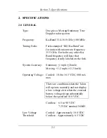
Page 7: ...ency will have that frequency clearly labeled on the fork System Accuracy Stationary 1 mph 2km h Moving 1 2 mph 2 3 km h Corded 10 8 to 16 5 VDC 800 mA max There are conditions when the Talon will operate normally and not display a low voltage alert when the external battery voltage drops substantially below the specified 10 8 VDC Operating Voltage Cordless 6 5 to 9 0 VDC 7 2 VDC nominal NiMH Low ...

Page 8: ...Diode protection No damage if supply leads reversed Electronic Components 100 solid state integrated circuits microprocessor and Digital Signal Processor Operating Temperature 22 F to 140 F 30 C to 60 C 90 relative humidity at 37 C non condensing Dimensions Unit Height 3 56 9 04 cm Width 3 0 7 62 cm Depth 7 25 18 42 cm Weight 1 lb 12 oz 79 kg Handle Height 5 75 14 6 cm Width 2 17 5 51 cm Depth 3 6...

Page 9: ...t Comparison of quartz crystals done periodically 5 minutes maximum upon every mode change and at the time of lock Err 4 displayed if an error is found Lock Time Instantaneous PATROL window Displays Doppler patrol speed Target window Displays truncated target speed Lock Fast Window Displays locked target speed or fastest vehicle in Fast mode Display Type Active matrix Liquid Crystal Display LCD Ba...

Page 10: ...36 km h Moving Same direction 10 dB for target difference speeds of 5 to 25 mph 8 to 40 km h Stationary 10 to 210 mph 16 to 255 km h Moving Patrol 10 to 80 mph 16 to 128 km h Typical patrol speeds to 120 mph 193 km h Target Opposite Dir Maximum target speed is a function of combined patrol and target speeds to 210 mph 336 km h Same Direction Minimum difference 3 mph 5 km h Maximum difference 0 65 ...

Page 11: ...ting voltage The transmitter is disabled but locked speeds will remain At approximately 6 0 VDC the Talon shuts itself off Radio Frequency RFI displayed during strong radio Interference frequency interference Active speed displays will blank during this condition Locked speeds will remain Error ERR x where x is a number displayed when an internal error in the operating system is detected Active sp...

Page 12: ...oving opposite selected Flashes in locked fastest mode Slower SLOWER displayed in moving same direction mode when operator selected if target is moving slower than patrol vehicle Flashes in locked slower mode Microwave Source Gunn Effect diode Beam Width 12 1 Polarization Circular Power Density Less than 5 mW cm2 at aperture Power Output 25 mW max 15 mW typ Side Lobes 25 dB below main lobe Receive...

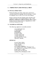
Page 13: ...omplete or parts are missing please contact Kustom Signals Customer Service Department at 1 800 835 0156 or 620 431 2700 3 1 MATERIALS SUPPLIED The following equipment is normally included Antenna Display Unit Corded Handle Dash Mount Mounting Pod Remote Control 55 mph Tuning Fork 30 mph Tuning Fork Speedometer Pulse Cable Operator s Manual OPTIONAL Fastest Vehicle Mode Same Direction Mode Battery...

Page 14: ...splayed or abnormal tones or noise in the audio An auxiliary power receptacle and cable which mounts under the dashboard and wires directly to the battery is available from Kustom 1 Mount the receptacle in the desired location using the hardware provided 2 Connect the black wire to the receptacle s mounting bracket Connect the white wire with Faston terminal to the rear plug of the receptacle Rout...

Page 15: ...nput cable using the splice connector provided Due to the vast amount of models makes and years of vehicles we have moved access to specific vehicle diagrams online where information can be better maintained and distributed Installation details can be accessed at http www kustomsignals com select radar fixed mount If your vehicle year make and or model is not listed or you need hard copies please ...

Page 16: ...ag deployment Normally this will be to the left or right of the steering wheel as space permits 3 Connect the Talon s power cable to the proper power source See Section 3 2 1 4 Momentarily press the PWR switch on the rear panel of the Talon Refer to Section 4 1 for location and function of the switches The Talon will proceed through an indicator test internal test and several other reliability tes...

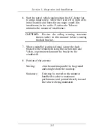
Page 17: ...Review the airbag warning statement shown earlier in this manual before securing the dash bracket 7 When a suitable location is found secure the dash bracket to the windshield using the suction cups and Velcro or permanently mount the bracket to the windshield 8 Position of the antenna Moving Aim the antenna parallel to the ground and straight down the roadway Stationary Unit may be moved on the m...

Page 18: ...IT DESCRIPTION 4 0 SIDE VIEW When the handle is attached the Talon operates in Stationary Mode only The trigger is used to Activate the transmitter Lock the active target speed Control the optional fastest vehicle feature Trigger 4 1 ...

Page 19: ...Section 4 Unit Description 4 1 REAR PANEL A B W C 4 2 V D U S E T R F G Q H P O I N J M L K ...

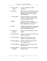
Page 20: ...ing voltage E RNG Range Bar graph display shows set level of Indicator range control F PATROL Displays the patrol vehicle speed G PWR Turns radar on or off H RNG Range Places the Talon in the range set mode Secondary function is the increment up control I Latch Press to unlock radar from pod or handle J Power Cable Permanently attached to the pod K Remote Control Accepts the remote control jack L ...

Page 21: ...lso used to turn the backlight feature on or off Q TEST Used to test the internal accuracy and to light all indicators Also used to access the Backlight feature R LOCK Fast Displays locked and fastest vehicle Display targets S FAST Indicator Lights when the fastest vehicle mode has been activated T SLOW Indicator Lights when in moving same direction slower mode selected U HOLD Indicator Indicates ...

Page 22: ... allows direct control of the following functions A HOLD Turns the microwave transmitter on and off B SAME OPP Switch selects either the target same or opposite direction modes C PAT SEL This switch will blank and recall a Patrol Select locked patrol speed It is also used for setting minimum patrol speeds and synchronizing the speedometer input ...

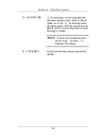
Page 23: ... modes turns fastest vehicle mode on or off 2 In moving same direction mode tells the processor the patrol vehicle is traveling slower than the target vehicle NOTE Fastest can be operated one of two ways See Sec 13 Options for details E LOCK REL Locks and releases target and patrol speeds ...

Page 24: ...Doppler From the antenna the signal travels to the Digital Signal Processing DSP where the speed of the patrol vehicle groundspeed is derived and displayed in the PATROL window With speedometer pulse input the DSP compares the indicated patrol speed from the vehicle s speedometer and is directed to look for the microwave low Doppler signal in an area around this speed If a low Doppler signal is fo...

Page 25: ...he target speed 120 50 70 The PATROL display would indicate 50 and the TARGET display would indicate 70 In the Same Direction mode the low Doppler and the difference Doppler signals are received and sent to the DSP The Difference Doppler is the speed difference between the patrol vehicle and the vehicle traveling in the same direction The Talon will display the patrol speed then add or subtract th...

Page 26: ...ed in terms of power density are 7 mW cm2 for X Band radar and 10 mW cm2 for K Band and Ka Band radar units Similarly the Occupational Safety and Health Administration OSHA a division of the U S Department of Labor recommends a 10 mW cm2 exposure limit for all three frequency bands Radiation Protection Guide 29 CFR Chapter XVII Subpart G Part 1910 97 This limit is clearly accepted by most reputabl...

Page 27: ...from 0 001 to 0 02 mW cm2 These measurements were obtained with the radars mounted inside vehicles as in normal operating conditions Since the NIST study other laboratories have duplicated these types of measurements producing consistently similar results For a free copy of the latest information regarding the safe human exposure standards please call or write Kustom Signals to request the RF Emis...

Page 28: ...s the unit will display 32 in the TARGET display window stationary mode or both target and PATROL display windows in the moving mode This will remain for approximately one 1 second The displays will clear and the unit will be operational 6 2 AUTOMATIC SELF TEST As long as the unit is turned on the Talon performs an internal accuracy test every 5 minutes or whenever the unit s mode of operation is ...

Page 29: ...hen return to normal operation If either the manual or automatic internal test fails the ERR indicator will be turned on and no further speed readings will be displayed The unit should be removed from service and sent to an authorized service center for repair INTERNAL TEST TOLERANCE 0 6 4 TUNING FORK TESTING Supplied with the Talon are two tuning forks 30 and 55 mph 45 and 80 km h These tuning fo...

Page 30: ...t speed display of the value stamped on the tuning fork 1 mph 1 km h 4 Repeat for the higher speed tuning fork 6 4 2 MOVING OPPOSITE DIRECTION TUNING FORK TEST 1 Attach the unit to the mounting pod and select moving mode opposite direction Press the SAME OPP switch on the remote if necessary to select opposite direction The OPP indicator will be lit 2 Ensure the HOLD indicator is off 3 If the spee...

Page 31: ...olerance is 1 mph 1 km h 6 4 3 MOVING SAME DIRECTION TUNING FORK TEST 1 From the moving mode press the SAME OPP switch on the remote control and place the unit in the Same Direction mode The SAME indicator will be lit 2 Lightly strike the higher speed tuning fork on a hard nonmetallic surface and hold it in front of the antenna The PATROL window should display the speed stamped on the fork 1 mph 1...

Page 32: ... These readings are only momentary and the proper readings should appear as the false overtones dissipate 3 Ensure that the Talon is in the transmit mode and the range control is set to maximum 4 If the proper readings cannot be obtained remove the unit from service and send to an authorized service center for repair 6 5 SPEEDOMETER VERIFICATION Before the Talon can be used with the speedometer pu...

Page 33: ...omparing the speedometer speed input and the true low Doppler patrol speed NOTE ONLY THE ACTUAL DOPPLER SIGNAL IS USED FOR PATROL SPEED THE SPEEDOMETER INPUT IS USED ONLY TO STEER OR GUIDE THE DSP TO LOOK FOR THE PATROL DOPPLER SIGNAL IN A SPECIFIC AREA IGNORING OTHER SIGNALS 4 During normal operation at patrol speeds below the minimum limit of 10 mph 16 km h or when a low Doppler signal cannot be...

Page 34: ... desired value appears Once the desired minimum value is selected the unit will time out in 2 seconds and the last displayed value will be accepted as the new minimum patrol speed 3 To display the existing minimum patrol speed press the PAT SEL switch one 1 time The current minimum patrol speed will be displayed in the PATROL window After two 2 seconds the Talon will return to normal operation 6 7...

Page 35: ... Signals recommends that all operators have prior training in radar speed monitoring devices Such courses are offered by Kustom Signals various state and local agencies and either IPTM Institute of Police Technology and Management or Northwestern University 7 1 SETUP For hand held stationary operation use the corded or cordless handle The corded handle requires external power from a portable batte...

Page 36: ...off Please note any interruption in the 110V power supplied to the charger will cause it to reset and begin the charging cycle again The optional fast charger allows charging directly from the vehicle s cigarette lighter receptacle The Talon may be used during charging with no decrease in the radar s effectiveness Charging will take less than 2 hours even with the radar in normal use The optional ...

Page 37: ...cked speed is preserved and the BATT indicator becomes steady When the voltage falls further the Talon shuts off 7 1 3 LOCATION 1 For stationary operation select an area that provides a good view of the traffic to be monitored 2 Check the immediate area for potential interference sources such as large reflecting signs in the direct path of the radar s microwave beam power substations and other pot...

Page 38: ...howing in the TARGET window Un will be displayed and the audio will be unsquelched To return to squelched audio repeat this step 7 1 6 RANGE Set the range control to the desired level Press the RNG switch and rnG will be displayed along with the current level 0 5 Also the range bar graph will indicate the current level The range can be increased or decreased by pressing the up arrow Range or down ...

Page 39: ...ed 3 Point the Talon at the intended target vehicle and pull and hold the trigger to complete the tracking history 4 Complete a tracking history on the target vehicle A Observe the target and surrounding traffic B Estimate the speed of the target vehicle C Listen to the audio pitch and compare the pitch to the estimate of speed in B D Observe the speed reading shown on the Talon s TARGET window It...

Page 40: ...can be recalled NOTE Some models due to state or local law require an automatic unlock feature The Talon software has a feature that when enabled will unlock all locked speeds when 15 minutes has elapsed 7 2 3 FASTEST VEHICLE MODE OPTIONAL FEATURE 1 To display the speed of the fastest vehicle in the radar s range pull the trigger twice within second holding it pulled the second time As long as the...

Page 41: ...de 5 Aim antenna directly at vehicles being monitored 7 3 2 STATIONARY MODE 1 Complete a tracking history as described in Sec 7 2 1 Step 4 2 To lock a speed press LOCK REL on the remote control To release a locked in speed press again See Sec 7 2 2 for details 3 To shut off the transmitter press HOLD on the remote The HOLD indicator will light and the TARGET display will blank locked speeds will r...

Page 42: ...ement action may be taken NOTE If an incorrect Patrol speed is obtained the operator can go in and out of HOLD quickly This will clear all previous speeds and a new patrol speed search will be initiated 7 4 1 HOLD MODE The Talon may be placed in the Hold mode non transmit by pressing HOLD on the remote control The HOLD indicator on the rear panel of the Talon will light and the displays will blank...

Page 43: ...vated C Changing the mode of operation moving to stationary 7 4 3 MOVING MODE PATROL SELECT To blank the flashing locked patrol speed display press the PAT SEL switch on the remote control Pressing the switch again will return the PATROL display 7 4 4 MOVING MODE FASTEST VEHICLE OPTIONAL FEATURE 1 With the unit operating in the moving mode observe traffic 2 The Talon allows two methods of fastest ...

Page 44: ... remote control The SAME indicator will be lit 2 While driving observe traffic traveling the same direction as the patrol vehicle 3 Complete a tracking history and verify the patrol speed agrees with the speedometer speed reading NOTE If an incorrect Patrol speed is obtained the operator can go in and out of HOLD quickly This will clear all previous speeds and a new patrol speed search will be ini...

Page 45: ...he patrol vehicle the operator should press and hold the FAST SLOW switch on the remote control The SLOW indicator will be lit 5 When the switch is released it will remain active for approximately two 2 seconds This will allow the operator time to lock the target speed reading ...

Page 46: ... the effective range of the Talon The patrol speed can also be affected by driving rain It is recommended that the operator compare the patrol speed reading and the speedometer reading frequently during rainy periods 2 Terrain can affect the range of the Talon Improper aiming of the antenna can cause the radar to appear to have short range If the target vehicle were on a slight incline the antenna...

Page 47: ...icle This difference speed may be placed in the PATROL window and used instead of the proper patrol speed See 8 2 below 3 The combined speed effect can occur when the patrol vehicle and the target vehicle are approaching each other at low speeds usually in the 25 to 35 mph 40 to 56 km h range each and at relative short distances usually less than 300 feet The radar unit sees a strong reflection fr...

Page 48: ...istorted audio Proper antenna mounting placement and aiming will eliminate most of the potential fan interferences 5 Vehicle ignition interference See Section 3 3 for further details NOTE Refer to the National Highway Traffic Safety Administration s Basic Training Program in RADAR Speed Measurement June 1991 for further information on interferences and training guides 8 2 GROUNDSPEED True groundsp...

Page 49: ...g radar it is still the responsibility of the operator to complete a tracking history on the target vehicle and verify the patrol speed with the patrol vehicle s speedometer Close observation of the patrol vehicle s speed reading is recommended to avoid possible confusion NOTE The Talon will not display patrol speeds below 10 mph 16 km h Operating moving radar in the rain and snow requires the ope...

Page 50: ... radar unit the mounting pod and remote control are not considered waterproof and if any liquid should get inside remove power immediately and send the unit in to a repair facility Prompt action can minimize any damage 3 If the Talon is used outside in rain or snow it should be wiped dry with a clean cloth as soon as practical 4 There are no user serviceable parts in the Talon The internal battery...

Page 51: ...Talon need repair or calibration from Kustom Signals Customer Service the following information is required 1 Department name return shipping address contact name at owning department and phone number 2 Complete description of failure or problem with unit Please describe in detail what the failure is and when it is observed EXAMPLE In moving mode targets are close to patrol vehicle before being di...

Page 52: ...fill They must be recycled at an appropriate facility or otherwise disposed of in accordance with local ordinances or they may be shipped back to Kustom Signals for disposal For more information on disposal facilities near you contact the Rechargeable Battery Recycling Corp RBRC at 1 800 8 BATTERY e mail rbrc rbrc com web page www rbrc com ...

Page 53: ...ence B State vs Shelt Ohio 1975 75 D O 3682 L 75 166 Establishes that the courts may take judicial notice of the reliability of moving radar Reference C Honeycutt vs Commonwealth Ky 1966 408 SW 2d 421 Court establishes that a tuning fork test is an accurate method of testing the accuracy of a radar unit and along with the visual observations of a trained operator is an accurate means of determinin...

Page 54: ...ior Court 72 N Y 2d 481 530 N E 2d 1273 1988 The court ruled that a trained operator who properly tested the radar observed the traffic and checked the patrol speed against the patrol vehicle s speedometer can accurately determine the speed of vehicles while the patrol vehicle is moving The court affirmed the lower court s ruling and accepted judicial notice of the radar in the moving mode of oper...

Page 55: ... within the specified technical parameters Each licensee must take effective measures to ensure the integrity of his communications system including periodic evaluation of receiver performance in order that undue air time not be consumed in repeating messages lost through poor effective receiver sensitivity the FCC said For the sake of convenience and simplicity of transmitter power measurement th...

Page 56: ...mobile communications systems To provide the Commission with a record of such units in use the licensees are required to list the number of speed detection units and the frequencies on which they operate at the time of renewal of their land mobile authorization Ordinarily this would be once every five years and would not be a significant addition to the renewal process the Commission noted This ac...

Page 57: ...ocket Unit will not complete Verify the power plug is test cycle or secure If the ERR message shows ERR indicator is lit power the unit off then back on If the problem persists remove unit from service and record the error code No target speed reading Verify that unit is set for during tuning fork test maximum range Verify unit is not in HOLD Unsquelch audio Listen for Doppler tone Lightly strike ...

Page 58: ... set properly Verify unit is aimed properly and the target is within range of the radar Unsquelch audio and verify that a Doppler tone is heard when targets are present If no Doppler tone is heard remove unit from service No patrol speed Verify unit is not in HOLD Verify the unit is aimed parallel to the ground and straight down the roadway Verify there are no obstructions directly in front of the...

Page 59: ...it from service Speedometer Check speedometer input verification shows 0 cable Verify it is connected to unit and to proper input wire Synchronize unit If above tests fail disconnect speedometer input cable press TEST switch and continue using radar No target readings in Verify unit is not in HOLD moving mode Verify the range control is set properly Verify proper patrol speed is displayed Verify p...

Page 60: ...operly Verify there are no obstructions between the unit and the target Weather conditions heavy rain snow and fog may affect the unit s range Check for electrical interferences Strong fan interference will reduce the operating range of the unit NOTE Use a shielded power cable KSI p n 155 2127 00 to eliminate the vehicle s electrical noise problems Remove the unit from service if the above tests f...

Page 61: ...r the option An example will be given to instruct the operator how to change the unit Option Add No AUTO UNLOCK 0 Automatic UNLOCK 1 Track through Lock 5 seconds 0 HOLD immediately after lock 2 Minimum Audio level 0 0 Minimum Audio level 1 4 Patrol Speed Blank 0 No Patrol Speed Blank 8 Fastest Push and Hold 0 Fastest Toggle 16 KSI Video Output 0 Gateway Output 32 DRU Style Output 64 Direct Video O...

Page 62: ...n the field 13 1 2 TRACK THROUGH LOCK TRIGGER OPERATION The Talon defaults to transmitting for 5 seconds after the trigger is released when locking a target This allows the target to be tracked after lock during this time If preferred the transmitter can be shut off immediately upon trigger release To select that option add 2 to the Options total 13 1 3 MINIMUM AUDIO LEVEL The Talon defaults to al...

Page 63: ...long as the operator holds down the FAST switch and for 2 seconds after it is released The alternate mode is toggle in this mode fastest is alternately turned on or off by pressing the FAST switch If fastest toggle mode is desired add 16 to the Options total 13 1 6 INTERFACE OUTPUT PROTOCOL The Talon defaults to allow the radar unit to interface the KSI Eyewitness video or giant display equipment ...

Page 64: ...ecrease the number for the value needed To make these changes permanent until changed again depress the MODE switch once When the options have been accepted the unit will automatically return to radar mode EXAMPLE The operator wishes to permanently change the operation of the unit to the following Automatic Unlock 1 no Patrol Blank 8 toggle Fastest function 16 Gateway unencrypted output 32 and MPH...

Page 65: ...Operator s Manual and shall not apply to Equipment which has been defaced or damaged through normal usage The Owner or Lessee shall use the Equipment in accordance with the manufacturer s operational instructions and failure to do so shall void this Limited Warranty 3 Exclusive Remedy The Owner s or Lessee s exclusive remedy under this Limited Warranty is limited to repair to the manufacturer s op...

Page 66: ...ILITY FOR THE LOSS OF USE OF THE EQUIPMENT WARRANTED LOSS OF TIME INCONVENIENCE COMMERCIAL LOSS OR OTHER DIRECT CONSEQUENTIAL SPECIAL OR INCIDENTAL DAMAGES KUSTOM SIGNALS INC MAKES NO WARRANTIES OF ANY KIND OTHER THAN AS HEREIN EXPRESSLY PROVIDED EXPRESSED OR IMPLIED AND SPECIFICALLY DISCLAIMS THE IMPLIED WARRANTIES OF MERCHANTABILITY AND OF FITNESS FOR A PARTICULAR PURPOSE SOME STATES DO NOT ALLO...

Page 67: ...his information will vary by vehicle make and model year Kustom Signals recommends contacting the vehicle manufacturer and following their instructions with respect to mounting of radar units and other equipment For additional mounting suggestions please contact the Kustom Signals Customer Service Department Kustom Signals cannot accept any liability for equipment which has been mounted in conflic...

Page 68: ...UNIT SERIAL NUMBER_____________ ON DUTY TEST OFF DUTY TEST DATE TEST FORK READ DRIVE RADAR SIGN TEST FORK READ DRIVE RADAR SIGN COMMENTS ...

Reviews: