background image


17 

Appendix 2 


Fine Azimuth Adjustment 

 
This can be done using an oscilloscope and a test record or by using good records in a good system 
and listening to the sound.  Cartridges with fine profiles (VDH, Microline etc.) are more sensitive to 
this adjustment.  On the other hand cheaper cartridges are not made so well, making fine adjustment 
more useful. 
 
With an oscilloscope we measure the differences in crosstalk between both channel. The idea is that 
on both channels this is equally small.  For that we need a test record with tracks recorded for left and 
right  channels  separately.    Then  we  compare  crosstalk  from  the  left  channel  on  the  right  channel- 
which  is  a  very  small  signal,  to  the  same  type  of  signal  from  the  other  channel.    By  adjusting 
azimuth, crosstalk on both channels should be made equal. 
 
Listening from LP: 
Start  listening  with  the  tube  in  zero  position,  with  the  marking  lines  aligned.    Listen  to  the  sound-
stage, the focus  and the stability of the instruments.   Release the two locking screws and rotate the 
Allen key so that tube rotates for approximately the width of the mark.  Listen and then rotate tube 
for  a  similar  amount  in  the  opposite  direction  and  again  listen.    Adjust  the  arm  to  the  position  in 
which the best sound was obtained.   In this position make further adjustments by turning the Allen 
key for a quarter turn in one direction, listening and then turning a quarter turn in the other direction 
and listening. 
 
Continue this process making ever decreasing adjustments, 1/8 of a turn, then 1/l6 and so on. When 
optimum  results  are  obtained  fix  the  locking  screws.    To    remember    the  position  of  the  azimuth, 
imagine that the inserted Allen key acts as a dial on the clock. 


NOTE: During fine adjustment only gently fix locking screws during listening. 

 
 The  adjustment  screw  is  highly  sensitive  and  the  smallest  pressure  on  the  Allen  key  will  alter  the 
azimuth and sound. 
Do not attempt any adjustment when the locking mechanism is locked.  Although no  damage can be 
done. 
Significantly  improved  sound  can  be  obtained  by  paying  attention  to  azimuth  adjustment  prior  to 
final VTA adjustment. 


Summary of Contents for 4POINT 9

Page 1: ...1 KUZMA 4POINT 9 TONEARM Instruction manual Serial Number 2019 09 KUZMA LTD INSTRUCTION MANUAL FOR 4POINT 9 tonearm ...

Page 2: ... description 3 Product registration and warranty extension 3 1 Technical data and unpacking 4 2 Basic set up 5 6 3 Setting up the tonearm 7 9 4 Adjustment of tracking force 8 Adjustment of tangential geometry 8 Adjustment of VTA 9 Adjustment of azimuth 10 11 Adjustment of bias 12 Adjustment of cueing device 12 Maintenance 12 Transport 12 13 Troubleshooting 13 Technical appendixes set up cartridge ...

Page 3: ...an Allen key A feature of the tonearm is a unique detachable headshell The electrical connection is via standard clips but the headshell can be simply removed by unscrewing with an Allen key The headshell is fixed with a precise hexagonal locking system giving the same rigidity as with a fixed headshell The tonearm is fixed on the turntable arm board via the Kuzma arm base VTA is adjusted by raisi...

Page 4: ...refully and remove top covers The tube with vertical bearing points is packed separately tube assembly on the top of the box Please do handle with care and when put aside ensure that nothing is touching the bearing points Bear in mind how you will handle it with the output cable which is fixed on the tube assembly during transport First remove the arm base and prepare it for fixing onto the turnta...

Page 5: ...ck when mounting the arm on other turntables that you allow enough clearance for the counterweight and correct position of the tube in relationship to the platter Fig 3 4 Due to the special bearing construction there is only a limited arc in which the arm tube can travel in a horizontal way Fig 3 Kuzma arm base Fig 4 Arm base on arm board Arm tower Insert the arm tower into the arm base Ensure tha...

Page 6: ...embly so that both vertical spikes points fit into the appropriate vertical bearing cups Then position the tube into the armrest Fig 7 7a Fig 7 Tube with cable Fig 7a Vertical bearing spike cup Cable assembly Remove cable from the tube assembly by releasing the black cable holder from the transport position with the 1 5 mm Allen key Fix it to the empty pin at the back of the arm tower Fix it in su...

Page 7: ...crews When fixing cartridge clips be sure that you do not damage wires under the insulation tubes If you wish you can fix the fingerlift on the side of the headshell no key required Fig 9d Headshell removal and fixing This tonearm has a detachable headshell and fixing and positioning it has no negative effect on tonearm performance The whole headshell is fixed with one Allen key 2 mm Fig 9a c Inse...

Page 8: ...force by using a balancing scale which must be at record height Rotate the counterweight towards the tube Rotation for one dots will change tracking force by approximately 0 15 g Set the tracking force suggested by cartridge data Check that the cueing device is at the correct height See Paragraph 9 5 Tangential geometry set up Put a record on the platter cue cartridge lift up cartridge from the re...

Page 9: ... is in the range of 30 mm If you need to have tonearm VTA adjustment higher then add the black VTA ring between the arm base and VTA screw This will give you an extra 5 mm or 20 mm height You will find them with the accessories See Fig 12b 12c Thinner VTA ring you do not fix on pillar with screw If you find out that tonearm is positioned too low below the platter you can purchase plastic height ri...

Page 10: ...C plate with the accessories Fig 13 Arm rest plate Fig 13a Arm rest one spacer plate 7 Azimuth adjustment To make azimuth adjustments release the two screws locking the mechanism on the centre top of the tonearm tube with Allen key 2mm Under the main tube is a tiny rod with a hexagonal screw Insert the Allen key 2 mm into the screw it may feel loose rotate it slightly and it will alter the azimuth...

Page 11: ...11 Fig 14b Azimuth 0 Fig 14c Azimuth left Fig 14d Azimuth right ...

Page 12: ...rd then the cueing device can be raised or lowered This can be done simply by using Allen key 1 5 mm Insert key into screw on side of arm rest Release screw raise or lower device and retighten Rotation of the cueing device may affect the drift of the cartridge while travel vertically down The cueing device may lift slightly as the screw is retightened Do not over tighten as this may cause the cuei...

Page 13: ...ner grooves check that the position of the tonearm is correct with a protractor for distance and that the spindle to arm base distance is 212 mm Otherwise you need to rotate arm tower Headshell cannot be removed check that the screw is adequately released with Allen key Fig 10c Headshell identification Different length 4Points use different headshells due to different offset angles 4Point 9 is mar...

Page 14: ...h still has optimum tracking distortion 1 Ensure bias is on minimum or switch off 2 Place protractor over spindle on platter Note If you have difficulty seeing the cantilever it may help to raise the arm a few mm taking care that the protractor does not rotate This also prevents tilting of the cantilever due to the effect of bias force It may also be helpful to fix the platter by inserting a wedge...

Page 15: ...r viewing Fig 15 9 If stylus is in front of point B pull the cartridge forward along side in the slots of the headshell for approximately the same distance S as stylus is overhanging zero point B If it is behind point B push cartridge backwards towards the pivots of the tonearm for distance S Fig 16 Fig 16 Stylus tip is in front of zero point B 10 Now rotate protractor and again position stylus at...

Page 16: ...ds and realign it at zero point A If stylus is still behind the B point the cartridge should be pushed back and realign at zero point A and realigned again at zero point B 12 Continue until the stylus is in alignment at both points REMEMBER STEPS a Put stylus at zero point A and by rotation align cantilever along XY line b Align cantilever along XY line at zero point B by rotating protractor and s...

Page 17: ...y of the instruments Release the two locking screws and rotate the Allen key so that tube rotates for approximately the width of the mark Listen and then rotate tube for a similar amount in the opposite direction and again listen Adjust the arm to the position in which the best sound was obtained In this position make further adjustments by turning the Allen key for a quarter turn in one direction...

Page 18: ...ctions on test record 2 If mistracking is apparent increase or decrease bias until minimum mistracking is found If mistracking is heard on the right channel only then the bias is too low if on both channels the bias is too high or the trackability limit of the cartridge has been reached 3 Finally further decrease mistracking by increasing tracking force to the maximum Recommended for the cartridge...

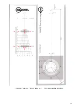
Page 19: ...19 Cartridge Protractor Not in correct scale Tonearm mounting protractor A X Y S B X Y ...

Reviews: