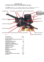
background image


1


KUZMA 4POINT TONEARM             


Instruction manual             

Serial Number: …..


2020-04 


Summary of Contents for 4Point

Page 1: ...1 KUZMA 4POINT TONEARM Instruction manual Serial Number 2020 04 ...

Page 2: ...tment of tracking force 9 Adjustment of tangential geometry 9 Adjustment of VTA 10 Adjustment of azimuth 10 Adjustment of bias 11 Damping 11 12 Adjustment of cueing device 13 Maintenance 13 Transport 13 Troubleshooting 14 Technical appendixes set up cartridge 15 19 Protractors 20 headshell lock vertical paddle vert paddle lock horizontal bearing assembly VTA tower VTA lock Wire loop pin for cable ...

Page 3: ...ht with which the tracking force can be finely adjusted Azimuth can be adjusted in small repeatable increments with zero play by means of an Allen key A feature of the tonearm is a unique detachable headshell one spare included as standard The electrical connection is via standard pins but the headshell can be simply removed by unscrewing with an Allen key The headshell is fixed with a precise hex...

Page 4: ...ing 264 mm Effective mass 18 g VTA adjustment yes Azimuth adjustment yes Bias adjustment yes Vertical damping yes Horizontal damping yes Detachable headshell yes one extra supplied Cables silver Arm mount Kuzma 212 mm Optional biwiring wiring extra headshells azimuth lock VTA scale fine horizontal bearing assembly vertical bearing point azimuth adjustment bias ...

Page 5: ...hree screws M5 into this ring which will then hold the armbase very tightly Be sure that you position the armbase so as to give access to an Allen key for fixing arm into armbase towards the back of the turntable Also check when mounting the arm on other turntables that you allow enough clearance for counterweights and correct position of the tube in relationship to the platter Due to the bearing ...

Page 6: ...that the bias thread is fixed and gently rotate horizontal bearing assembly from one to another extreme It is only possible to make approximately of a turn It is normal to feel slack in the bearings Tube assembly Carefully take the tube assembly with cable there is also a heavy connection box and gently position it around the horizontal bearing assembly so that both two points will fit into the ap...

Page 7: ...m screws When fixing cartridge pins be sure that you do not damage wires under insulation tubes If you wish you can fix fingerlift at the side of the headshell no key required Fig 7A Headshell removal and fixing This tonearm has a detachable headshell and fixing and positioning it has no negative effect on tonearm performance The whole headshell is fixed with one Allen key 2 mm Insert it in the to...

Page 8: ...e sure to fit the plastic rings that separate counterweights and at the same time allow them to fit together See Fig 2 and counterweight configuration Knowing the approximate mass of the cartridge enables choice of the correct configuration of different counterweights Aim for roughly zero balance Even if the counterweights are not screwed to the end as long as you rotate two against each other the...

Page 9: ...ig 2 4 Adjustment of tracking force Balance the tonearm with the tracking scale which must be at record height Rotate the smaller counterweight towards the tube Rotation for one turn observe red dots will change tracking force for approximately 0 1g If you are unable to obtain the correct tracking force add or remove main counterweights By rotating two counterweights along the thread you can obtai...

Page 10: ...e However take into account what is the optimal VTA by listening Once you find out the correct VTA rotate outer ring of the VTA main knob and position it into null position This is now your starting point for very fine tuning Fig 8 VTA tower side rough scale 7 Adjustment of azimuth To make azimuth adjustments release the two screws locking the mechanism at the centre top of the main tonearm tube w...

Page 11: ...t records with blank space where the tip of the needle sits on the surface rather than in the groove Fig 9 9a See appendix 3 9 Damping This tone arm has two independent damping systems The lower trough is for horizontal damping and the second trough on the arm tube assembly is for vertical damping Fig 1 Both troughs are removable The horizontal holder with paddle is permanently fixed on the horizo...

Page 12: ... by holding a screw with Allen key 1 5mm and ACW rotation with fingers of the small black nut Adding damping oil First insert silicone damping oil into the troughs Let the liquid settle before adding more Stop filling when you reach the silver lines about 3mm below the edge of the troughs Removing trough Removing trough using Allen keys 1 5 mm vertical fig 11 and 2 5 mm horizontal fig 12 1 Release...

Page 13: ...tenance The bearing does not need maintenance Clean dust from the tonearm with a dry cloth and use a soft cloth and alcohol to remove silicone oil 12 Transport During transport the tube assembly must be removed from the horizontal bearing assembly To do this you must remove the vertical paddle Remove vertical trough and reposition cable on the tube assembly Fig 3B REMOVE ALL SILICONE OIL Return fi...

Page 14: ... the record check that position of the tonearm is correct with protractor for distance and spindle to armbase distance is 212 mm 2B Cartridge is not reaching inner grooves check that position of the tonearm is correct with protractor for distance and spindle to armbase distance is 212 mm 3 Headshell cannot be removed check that the screw is released enough with Allen key Kuzma Ltd Hotemaze 17A SI ...

Page 15: ...n this case 60 mm has been chosen as the inner groove and 146 mm as the outer groove which still has optimum tracking distortion 1 Ensure bias is on minimum or switch off 2 Place protractor over spindle on platter Note If you have difficulty seeing the cantilever it may help to raise the arm a few mm taking care that the protractor does not rotate This also prevents tilting of the cantilever due t...

Page 16: ... line x y though stylus will probably not be at zero point B Raise the cueing device a bit for better viewing Fig 15 9 If stylus is in front of point B pull the cartridge forward along side in the slots of the headshell for approximately the same distance S as stylus is overhanging zero point B If it is behind point B push cartridge backwards towards the pivots of the tonearm for distance S Fig 16...

Page 17: ...ore backwards and realign it at zero point A If stylus is still behind the B point the cartridge should be pushed back and realign at zero point A and realigned again at zero point B 12 Continue until the stylus is in alignment at both points REMEMBER STEPS a Put stylus at zero point A and by rotation align cantilever along XY line b Align cantilever along XY line at zero point B by rotating protr...

Page 18: ...y of the instruments Release the two locking screws and rotate the Allen key so that tube rotates for approximately the width of the mark Listen and then rotate tube for a similar amount in the opposite direction and again listen Adjust the arm to the position in which the best sound was obtained In this position make further adjustments by turning the Allen key for a quarter turn in one direction...

Page 19: ...ctions on test record 2 If mistracking is apparent increase or decrease bias until minimum mistracking is found If mistracking is heard on the right channel only then the bias is too low if on both channels the bias is too high or the trackability limit of the cartridge has been reached 3 Finally further decrease mistracking by increasing tracking force to the maximum Recommended for the cartridge...

Page 20: ...20 Cartridge Protractor Not in correct scale Tonearm mounting protractor A X Y S B X Y ...

Reviews: