
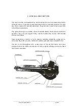


Summary of Contents for Stogi S
Page 1: ......
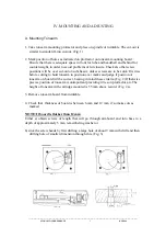
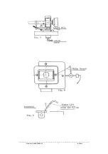
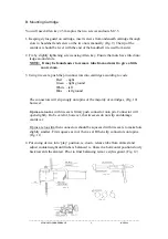
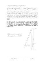
The Kuzma Stogi S is a high-quality turntable tonearm constructed with precision engineering. To help you fully leverage its features, we provide a comprehensive Instruction Manual available for free download at 88.208.23.73:8080. This manual offers step-by-step guidance on setup and usage, ensuring optimal performance for your audio system.
Page 1: ......


