background image

6

ESP4000  ·  G

etting S

tar

ted

ESP4000 · Getting Started 

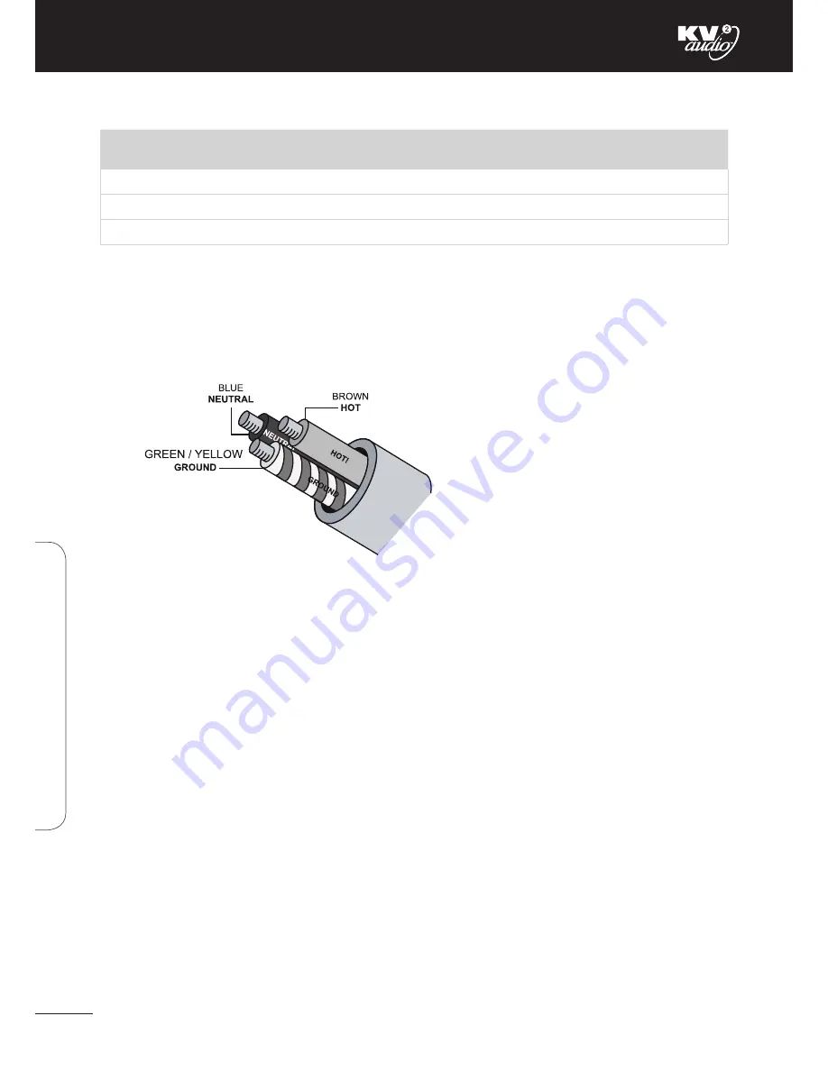
AC Cable Colour Coding

If the colours referred to in the diagram don't correspond to the terminals in your plug, use the following guidelines: Connect 
the blue wire to the terminal marked with an N or coloured black. Connect the brown wire to the terminal marked with an L 
or coloured red. Connect the green and yellow wire to the terminal marked with an E or coloured green or green and yellow.

CAUTION: THE ESP4000 REQUIRES A GROUND CONNECTION. ALWAYS USE A GROUNDED OUTLET AND PLUG.

Safety Summary

To reduce the risk of electric shock, disconnect the amplifier from the AC mains before installing the audio cable. Reconnect 
the power cord only after making all signal connections. Connect the amplifier to a two pole, threewire grounding mains 
receptacle. Mains plug shall remain easy to operate. Amplifier must be powered from the same phase. 

The receptacle must be connected to a fuse or circuit breaker. Connection to any other type of receptacle poses a shock 
hazard and may violate local electrical codes. Do not allow water or any foreign object to get inside the amplifier. Do not put 
objects containing liquid on or near the unit. To reduce the risk of overheating the amplifier, avoid exposing it to direct 
sunlight. Do not install the unit near heatemitting appliances, such as a room heater or stove. This amplifier contains 
potentially hazardous voltages. Do not attempt to disassemble the unit. The unit contains no user serviceable parts, repairs 
should be performed.

Power cable color coding

Current Draw per Power Supply Input

Current Draw

115V Mode

230V Mode

Max Long Term Continuous

20 A rms

10 A rms

Burst Current

30 A rms

15 A rms

Short Term Peak

80 A peak

40 A peak

Summary of Contents for ESP4000

Page 1: ...n is to constantly develop technologies that eliminate distortion and loss of information providing a true dynamic representation of the source Our aim is to create audio products that absorb you place you within the performance and deliver a listening experience beyond expectations ...

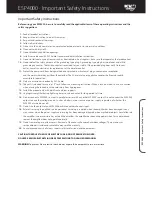
Page 2: ...it is intended for use in a 19 rack Follow the mounting instructions When a rack on wheels is use use caution when moving the loaded rack to avoid injury from tipping over 14 Install the product only with both front and rear supports 15 Unplug this amplifier during lightning storms or when unused for long periods of time 16 Do not connect a ESP4000 s output in parallel or series with any other ESP...

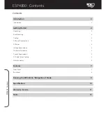
Page 3: ...Mounting 4 Cooling 4 AC Power Requirements 4 AC Power 4 Voltage Requirements 5 The Power Connector 5 Current Requirements 5 AC Cable Colour Coding 6 Safety Summary 6 Features 7 Front Panel 7 Rear Panel 8 Running the ESP4000 in Bridge Mono Mode 9 Specifications 10 Warranty Service 11 Notes 12 Contents ...

Page 4: ... can be dangerous This is a very highpowered device that can put out high voltages and sizeable currents Always use safe operating techniques with the ESP4000 FOR YOUR SAFETY READ THE IMPORTANT PRECAUTIONS SECTION AS WELL AS THE INPUT OUTPUT AND POWER CONNECTION SECTIONS OF THIS MANUAL ESP4000 part number KVV 987 215 250V KVV 987 208 230V KVV 987 214 115V Front Panel Rear Panel Side Panel Applicat...

Page 5: ...ent requirements as well as electrical safety issues is critical to the safe operation of the ESP4000 Cooling The ESP4000 has a comprehensive cooling system featuring chassis sealed PCB board mounting and shock mounted speed controlled fans This means that the cooling system never drives air across PCB boards connectors or components ensuring prolonged electronic component lifespan and minimizing ...

Page 6: ... at the service entry The Power Connector The ESP4000 requires grounded outlets It is very important that the amplifiers AC supply be properly grounded in order to operate safely and properly Use the PowerCon AC cable wiring diagram overleaf to create international or special purpose power connectors Power connector assembly Current Requirements Each of the ESP4000 s power supply inputs require ap...

Page 7: ...ole threewire grounding mains receptacle Mains plug shall remain easy to operate Amplifier must be powered from the same phase The receptacle must be connected to a fuse or circuit breaker Connection to any other type of receptacle poses a shock hazard and may violate local electrical codes Do not allow water or any foreign object to get inside the amplifier Do not put objects containing liquid on...

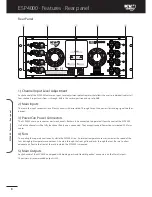
Page 8: ...hannel This feature is active so long as the switch is left un pressed The RMS limiting is deactivated when the switch is depressed 4 Power On Thermal These are dual colour LED s When green they indicate that the Power Switch is ON and that channel of the amplifier is powered up When red they indicate that channel has overheated and shut down The unit will Auto Reset after it cools down to a safe ...

Page 9: ...e ESP4000 uses one connector per two channels Both must be connected to operate all four channels of the ESP4000 Half of the channels will be fully functional if only one is connected They accept standard PowerCon terminated AC Mains cables 4 Fans The cooling fans operate continuously while the ESP4000 is on An internal temperature sensor increases the speed of the fans during high temperature con...

Page 10: ...negative side of the high powered loudspeaker load This has correctly connected the high powered loudspeaker load to both CH1 CH2 ready to be driven in Bridge Mono mode To ensure the amplifier channels are working together correctly in this mode you must feed the Main Input Signal into ONLY CH1 before linking across to CH2 with a special phase reversal lead To make this lead you must modify a stan...

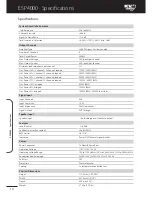
Page 11: ...ded 1000W 800W RMS Out Power 16Ω bridged 600W RMS Out Power 8Ω bridged 1000W RMS Out Power 4Ω bridged 1600W RMS 2000W short term Signal Input Input Channels XLR Input Sensitivity 1 55V Input Impedance 20kΩ balanced Signal Output XLR Through Speaker Input Speaker Input 4x Binding posts Neutrik Speakon Features Level Control to 0dB Loudness bass enhancement 6dB 60Hz RMS Limiter On Off Indicators Pow...

Page 12: ...returned to an authorized distributor service centre or shipped directly to our factory Because of the complexity of the design and the risk of electrical shock all repairs must be attempted only by qualified technical personnel If the unit needs to be shipped back to the factory it must be sent in its original carton If improperly packed the unit may be damaged To obtain service contact your near...

Page 13: ...ESP4000 Notes 12 ESP4000 Notes ...

Page 14: ...KVV120054 00 06 0 KV2 Audio International Nádražní 936 399 01 Milevsko Czech Republic Tel 420 383 809 320 Email info kv2audio com www kv2audio com The Future of Sound Made Perfectly Clear ...

Reviews: