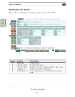
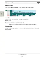
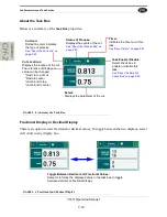
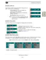
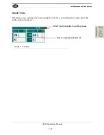

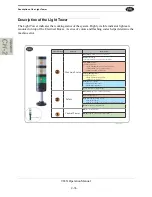
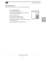
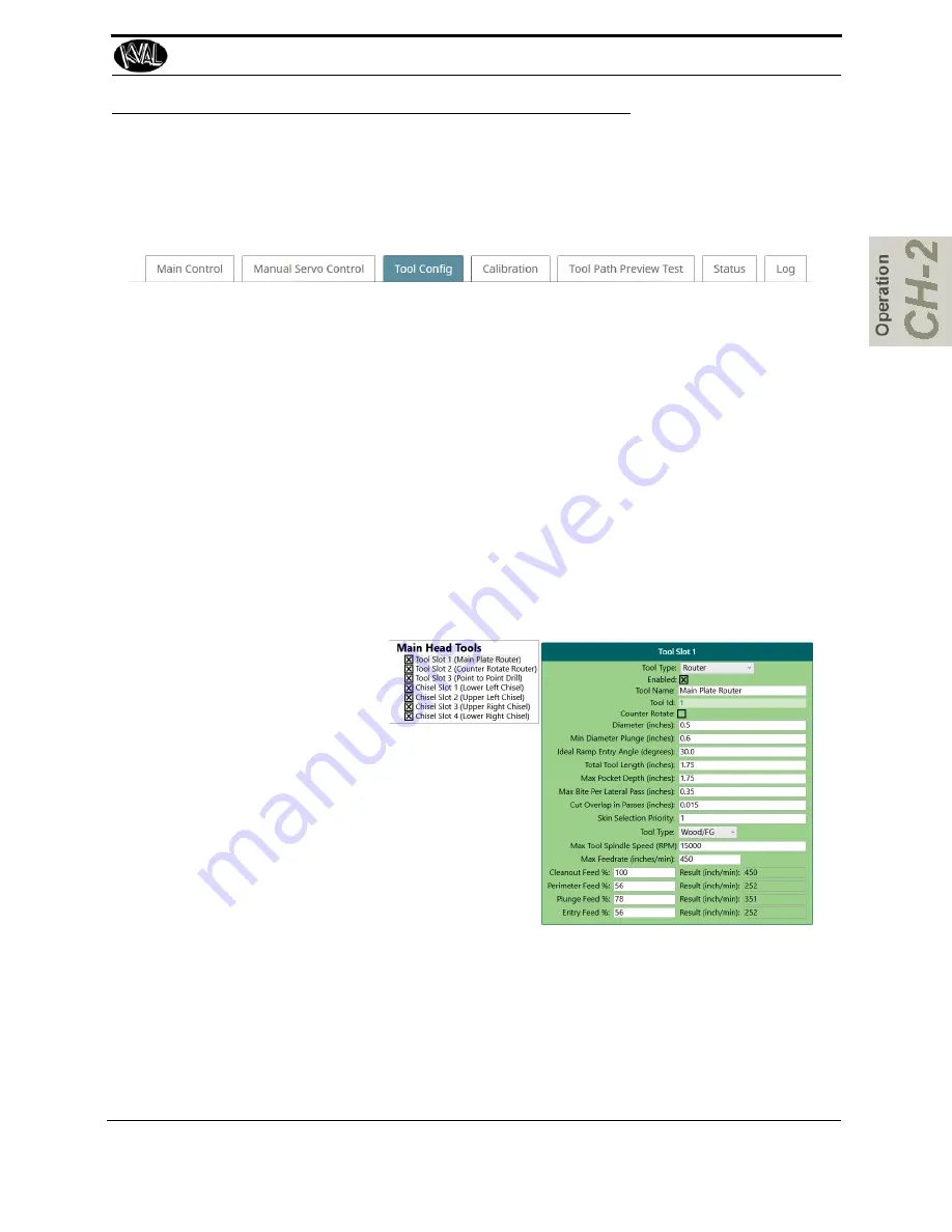
About the Tool Config Tabs
2-29
965X Operation Manual
About the Tool Config Tabs
This section includes descriptions of the
Tool Config
screen
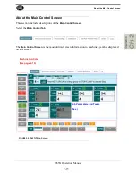
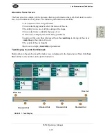
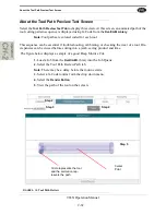
To display the
Configuration Screen
, select the
Tool Config
tab and choose the desired tool.
At this screen specifications of the tool is entered and saved to the database. This information is
valuable to compute and provide the most precise cut available.
The
Tool Config Screen
contains:
• Access to tools
• Pop-up menus to enter information about each tool (Specifications, Router or Drill)
• The ability to enable or disable specific tool slots
• The ability to name the tools to familiar names.
• The ability to lock and unlock the ability to enter data.
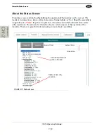
List of Tools
Available
Pop-Up Menus: enter
tool data.(Router,Drill
and Chisels (opt)
Summary of Contents for 965X
Page 103: ......


