background image

   Step 2: Calibrate the Stops

3-11

965X Operation Manual

Step 2: Calibrate the Stops

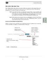
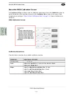
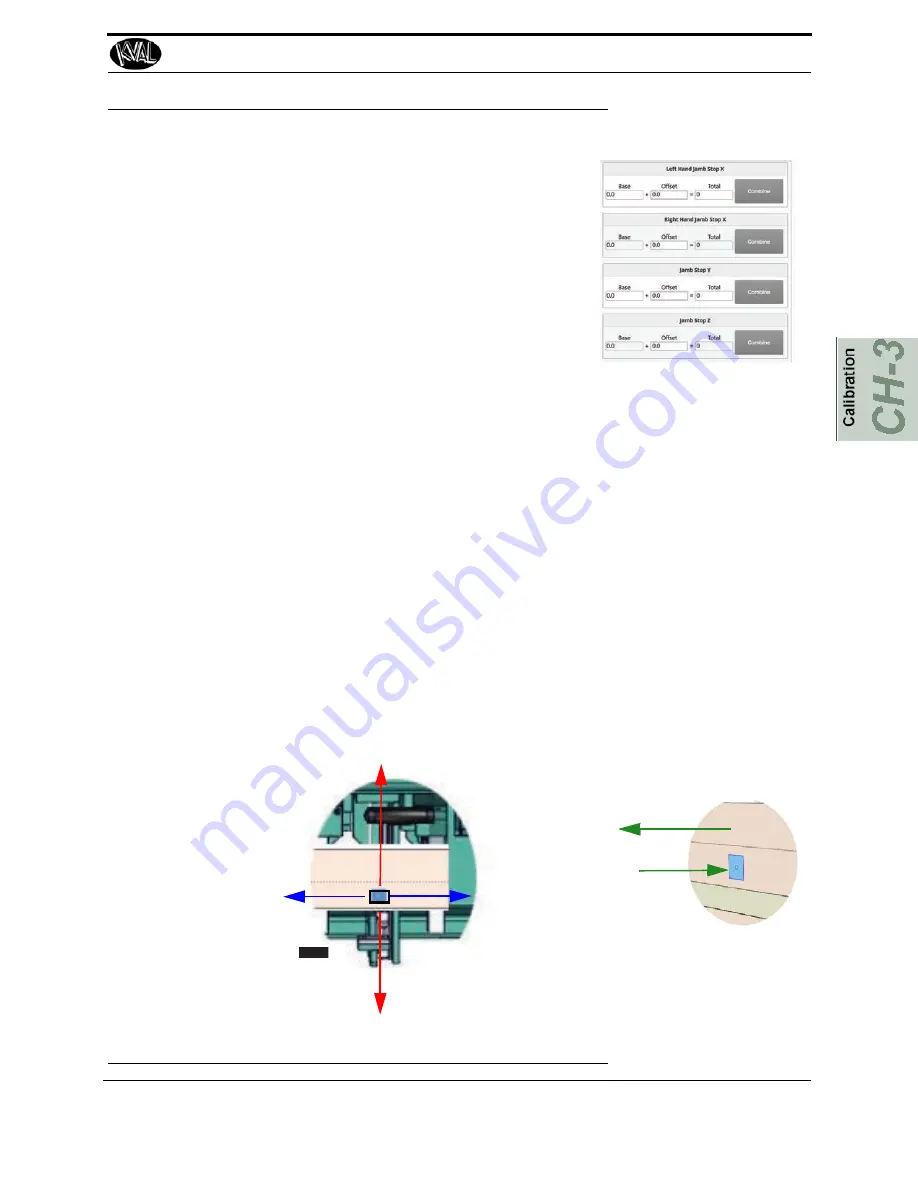
At the

 Calibration Screen

, select 

Jamb Stops

Procedure to Calibrate the Stops

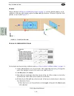
In this calibration process, cut a known shape on the jamb. Mea

-

sure the 

location

 of the cut.

1. 

Before calibrating the tools, make sure the 

Tool Con

-

figurations

 are up to date. 

See “About the Tool Config 

Tabs” on page 2-29 .

2. 

Create a 

Job

 of your choice.

For Example:

Create a 2.0 '' square, with chiseled corners, a middle predrill 44.0 '' from the top reference.

3. 

Add the 

Job

 to the 

Queue

4. 

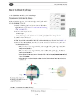
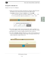
Once the cut has been made, check the location and shape of the cut. See 

Figure 3- 4 .

5. 

Perform the

 Left Hand Rule

 from the rear of the machine to determine axis direction. 

See illustration below.

• If the location is out of specification in the 

length

 of the jamb edge, the 

X-Axis 

needs to be adjusted.

• If the location is out of specification in the 

width 

of the jamb edge, the 

Y-Axis


needs to be adjusted.

• If the plunge cut depth is out of specification, check the 

Configuration Menu

 then 

verify the 

Z-Axis.

• If the shape is out specification, adjust for the best location then check the tool 

calibrations.

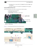
FIGURE 3- 4.

Procedure to Calibrate a Stop

Reference from back of 

machine. Point down to the cut 

using left hand rule.

X

Y

+

 Z

X

Y

Z

Summary of Contents for 965X

Page 1: ...Innovation Quality Honesty Operation Manual Published June 10 2021 Operation Manual 965X System 965X Jamb Machining System With KvalCAM ...

Page 2: ...f Automation GmbH Windows is a registered trademark of Microsoft Corporation All other products are trademarks or registered trademarks of their respective holders all rights reserved Reference to these products is not intended to imply affiliation with or sponsorship of Incorporated Contacting Customer Service For further information about this manual or other Incorporated products contact the Cu...

Page 3: ...ur user experience with our product that is the manual the machinery the software etc What was easy or difficult to use or to learn If you could change something about the design what would it be Please email your comments and suggestions for improve ment to userexperience inc com NOTE This is not a customer support email link For that please refer to the Customer Service contact information above...

Page 4: ...rated through the KvalCAM Software are also the property of the Licensor and are protected by applicable law 1 Definitions a KvalCAM Software means the KvalCAM computer application installed in the Machinery and written documentation and materials provided to you as well as any revisions or updates of such computer application and documentation b Install means storing of the KvalCAM Software in th...

Page 5: ...13 Getting Help from KVAL 1 15 KVAL Return and Warranty Policy 1 16 Send the Item 1 16 Acceptance of Return 1 16 Refund Turnaround Time 1 16 Kval Errors 1 16 Customer Errors 1 17 Shipper Errors 1 17 Warranty Replacement Parts 1 17 How to Download the Service Application 1 18 On Line Help 1 18 Download Application 1 18 Safety Sign Off Sheet 1 22 A Note to the Operator 1 22 About the 965X 2 2 Shape ...

Page 6: ...ls Section 2 16 About the Main Control Section 2 17 About the Sequence Control Section 2 18 About Jamb Clamp and Jamb Stop Section 2 19 About Speed Control 2 19 About the Jamb Support Selection 2 20 About the Jamb Support Blocks 2 20 Job Parameters and Task Section 2 21 About the Top Bar 2 22 Jamb Specs 2 22 Current Group 2 22 Status Message 2 22 About the Tasks Screen 2 23 Task Display to Jamb Cu...

Page 7: ...ation Option 3 4 Enter a Positive or Negative Number 3 5 How to Enter Calibration Data 3 6 About The Calibration Box 3 6 About Restore Points 3 7 About the 965X Calibration Screen 3 8 965X Calibration Screen 3 8 Calibration Selections 3 8 About Calibration Sequence 3 9 Step 1 Check the Carriage Location 3 10 Procedure 3 10 Step 2 Calibrate the Stops 3 11 Procedure to Calibrate the Stops 3 11 Step ...

Page 8: ...locks on the Vertical Jamb Clamp 4 9 Jamb Support Block Storage 4 9 Safety Light Curtain 4 10 If the Beam is Broken 4 10 To Resume Normal Operation after an Beam is Broken 4 10 About Sensors 4 11 Sensor Locations on Machine 4 11 Frame Sensors 4 11 Carriage Head Sensors 4 12 Location of Servo Motors and Valve Bank Locations 4 13 Servo Motor Locations 4 13 Valve Bank Locations 4 13 About the Electri...

Page 9: ...fety information is described in this section page 1 6 Lockout Tagout Guidelines Procedures describing Lockout Tagout page 1 10 Zero Energy to Start Up Procedure to power up your machine for the first time page 1 13 Getting Help from KVAL This section describes the method to con tact the KVAL Service Center for help The section includes how to get information from the specification plate tor provi...

Page 10: ... each adding unique functionality to the machine CNC Functionality The 965X a 3 Axis x y z CNC machine provides the operator with the ability to dictate mortise pattern depth radii location as well as pre drill pattern and depth Each variable is easily modi fied via our touch screen and KvalCAM program Key components include Beckhoff AC servo motors controller and industrial computer which in turn...

Page 11: ...indles are combined with tool path programming to eliminate chipping at the jamb edge A third hi fre quency 1 5HP spindle is utilized as a point to point pre drill system for hardware application Chisels The 965X is equipped with four 4 chisels mounted in pairs for the square hinges for higher end markets Safety An electronic zone sensor is included to prevent access to the machine while routers a...

Page 12: ...ut KvalCAM Descriptions of the KvalCAM user interface 3 Operation Inter face Descriptions of how to power machine line and operator inter face user screens 4 Calibration Descriptions of Calibration Rou tines and how to use the interfaces 5 Tour of the Machine Descriptions the assemblies on the machine Chapter Title Description 1 Introduction Safety Information 2 System IT Admin istration Descripti...

Page 13: ...5X Operation Manual KvalCAM Reference Manual Chapter Title Description 1 KvalCAM reference Description of the Interface 2 KvalCAM Examples Examples of Common Door Job Features 3 KvalCAM Common Terms Common terms associated with KvalCAM ...

Page 14: ...or illegible There are three types of warning labels or decals DANGER means if the danger is not avoided it will cause death or serious injury WARNING means if the warning is not heeded it can cause death or serious injury CAUTION means if the precaution is not taken it may cause minor or moderate injury Safety Guidelines In addition to the caution and warning labels affixed to this machine follow...

Page 15: ...ever perform any maintenance unless machine is at zero state Never clean the machine while it is running Never walk away from the machine while it is running When the Machine is ON The compressed air system connected to this machine should have a three way air valve for shut off and pressure relief All cylinders on machine are under high pressure and can be very dangerous when activated Before per...

Page 16: ...at different locations Before performing any repairs or mainte nance lockout and tagout must be installed at all locations All maintenance and repairs to electrical circuitry should only be per formed by a qualified electrician Still has power in OFF position Electrical Prior to performing any maintenance repairs cleaning or when clearing jammed debris you must disconnect tag out or lock out the e...

Page 17: ... you believe any part or operation of this machine is in violation of any health or safety regulation STOP pro duction It is your responsibility to immediately protect your employees against any such hazard Additional detailed safety guidelines are included in the operating instructions of this manual KVAL will be pleased to review with you any questions you may have regarding the safe operation o...

Page 18: ... tag on each disconnect Only each operator may remove their own lock and tag Important When many people are all working on the same machine you will need a multiple lockout device such as the one shown here Follow the P R O P E R lockout rule of thumb P Process shutdown R Recognize energy type electrical pneumatic mechanical etc O OFF Shut off all power sources and isolating devices P Place lock a...

Page 19: ...supply and pressure spring tension weight shifts etc 2 Inform all affected personnel of the eminent shutdown and the duration of the shutdown 3 Obtain locks keys and tags from your employer s lockout center 4 Turn off machine See Chapter 2 for power down and power up procedures 5 Turn the disconnect switches on ALL electrical and frequency panels to the OFF position Then push the red tab to pop it...

Page 20: ...completely removed and that all guards and safety devices are installed 10 Before removing the locks and tags the person who attached them shall inspect the equipment to ensure that the machine will not be put in an unsafe condition when re energized 11 The lock and tag can now be removed only by the person s who placed them and the machine can be re energized 12 The tags must be destroyed and the...

Page 21: ...nd tag This will ensure that all oper ators are in a safe place when the equipment is started Perform Visual Checks If the equipment is too large to see all around it station personnel around the area and sound the personnel alarm before starting the equipment If your operation is more complex your company s comprehensive safety procedure may involve additional steps You will need to ask your supe...

Page 22: ... work environment safe for you and your fellow workers Be sure to follow the P R O P E R lockout tagout procedures and that those around you do also Close the Cage Gate Verify all cage gates are securely closed Ensure all safety protocols are in effect ...

Page 23: ...d the serial number 3 phase volts electrical print number and air print number 2 Contact our customer support team In the U S and Canada call 800 553 5825 or fax 707 762 0485 Outside the U S and Canada call 707 762 7367 or fax 707 762 0485 Email address is service KVALinc com Hours 6 00 AM to 4 00 PM Pacific Standard Time Monday through Thursday 6 30 AM to 1 30 PM Pacific Standard Time Friday Air ...

Page 24: ... _______________ Send the Item Return the item to this address Kval Inc RMA ______ Kval Parts 825 Petaluma Blvd South Petaluma CA 94952 USA Acceptance of Return We can only accept items for a return if they are still in their original packaging and in undam aged resalable condition Returns are accepted within 45 days of purchase and with an RMA number issued by Kval Inc Returns after 45 days of pu...

Page 25: ...re than one 1 year after delivery will the product be covered under Warranty The repair replacement or payment in the manner described above shall be the exclusive remedy of Buyer for breach of Kval s warranty or for claims based upon failure of or defect in the products regardless of when the failure or defect arises and whether a claim however described is based upon contract warranty indemnity ...

Page 26: ... Windows 8 1 8 7 Vista XP and an internet connection our service team are able to connect run and troubleshoot your machine by way of the operator station Download Application 1 To download the application go the KVAL website http www KVALinc com 2 At the KVAL website select the Support tab Follow the instruc tions on the Support web page 3 Click the Download button to download the application tha...

Page 27: ...ams Below are samples of i e Explorer and Google web browsers Sample of Google Browser Located at the bot tom left of the screen Sample of i e Explorer Located at the bottom of the screen select the arrow and choose Save and Run 5 A pop up window is displayed Accept the request to run the program Note Security settings may differ from plant to plant If issues occur con tact your IT department ...

Page 28: ...our name The KVAL techni cian will use this field to identify this machine Description Enter machine Serial number and issue Indicator Green indicates there is a good connection to the service center If red there could be an issue with a LAN connection Check the connections in the plant 7 After the KVAL Support App is loaded and completed call the KVAL service center 1 800 553 5825 and have the te...

Page 29: ...How to Download the Service Application 1 21 965X Operation Manual Page Intentionally Left Blank ...

Page 30: ...my company s safety procedures I have read and understand these guidelines Machine Safety Concerns I have been given a tour of the machine and understand all the safety labels E Stops and the actions to take in case of an emergency I will make sure all guards are in place before operation I will turn off the compressed air before loading hardware staples screws etc I will turn off the electrical p...

Page 31: ...The following information is available in this chapter Section Name Summary Page About the 965X Process A summary of the 965X machining process page 2 2 Quick Start A summary of the steps to machine a jamb page 2 5 Powering Operations for the 965X Descriptions of power up power down homing and emergency stops page 2 10 Description of the Operator Interface Each interface screen described page 2 14...

Page 32: ...red by KvalCAM which allows rapid programming for door frame shapes FIGURE 2 1 965X Shape and Special Cut Highlights Highlights of the types of shapes and jamb types that can be processed include Hinges any radius or squared Face Plates including commercial squared corners T Strikes Ball Catch Mullions Astragals 3 Point Locks Dado Jamb and Header Cut Downs Angled Sill Cuts KvalCAM Driven ...

Page 33: ...iptions Jamb Properties include all the parameters to create a door frame The data is normally created remotely and saved into the database The properties are shown in the figure below Important The jamb parameters must be as accurate as possible for cut quality to be maximized Note To activate jamb data the Enable Jamb Properties check box must be selected FIGURE 2 2 Jamb Properties in th KvalCAM...

Page 34: ...ut a profile into the bottom of the jamb in order to fit into the sill Hinge Jamb Cut hinge pockets Cut the top dado Trim the bottom to a specific length External Cut a profile into the bottom of the jamb in order to fit into the sill Header Jamb Pocket and plates for hardware closers holders overhead latches Trim the length from one side Cut the stop down on the left and right side Hinge Pockets ...

Page 35: ...supply valve is turned on 2 Power up the 965X See How to Power Up the 965X on page 2 10 3 Select the KvalCAM shortcut 4 Home the 965X See Home the 965X on page 2 11 Step 2 Steps Before Processing Jamb Before operation the additional setup steps below may be required Select the Jamb Support Block From the pop up window choose the predetermined numbered block to match the jamb style Select the Jamb ...

Page 36: ...st be as accurate as possible for cut quality to be maximized Enter the quantity of jambs to be processed in the Door Qty box at the bottom of the screen Select the Add to Queue Button Step 4 Open the Main 965X Screen After the Job is loaded into Queued Jobs select the 965X tab At this screen the cuts to be performed are displayed and pre process streps can be made For detailed descriptions of the...

Page 37: ... process the jamb Note The process can either be controlled from the 965X Main screen or mechanically Foot Pedal Start Sequence button at the machine Step 5 Load the Jamb To extend the Door Clamps and Door Stops select the Jamb Stop Foot Pedal or the Toggle Stop button at the Main screen Load the jamb onto the machine Jamb Shelf Or ...

Page 38: ...ack and clamp to secure the jamb in the machine Danger Keep Hands away from the Clamps Step 7 Start Sequence After beginning the Start Sequence the operator must exit the cutting area beyond the Safety Light Curtain within 3 seconds If not exited the Start Sequence will cancel To restart press the Start Sequence again and leave the cutting area within the 3 second rule Or ...

Page 39: ... Step 8 Next Group Next Job or End Process Continue to the Next Group go to the Next Job or end the process Next Group If continuing to the Next Group select the Next Group button Tasks that are not being processed will have a gray background Repeat load jamb align jamb clamp jamb and process jamb Next Job If continuing to a different job repeat from Step 2 on page 2 5 If ending processing Shut do...

Page 40: ...and main air supply is turned on 2 Check that all E Stop buttons are out and safety gates are closed Note A pop up is displayed on the user screen if an E Stop is pressed 3 Make sure the electrical disconnect in the electrical cabinet is turned to the ON posi tion 4 Switch the green Control Circuit switch to the ON position 5 Push the green Start Machine button to boot up the machine Note Boot up ...

Page 41: ...n feed end of the machine 3 The machine will then move to its neutral position 4 The 965X is now ready for work How to Power Down 1 Park the Carriage Head by selecting the Park button on the Main Screen 2 Right click the Kval icon at the taskbar Select Exit from the drop down menu Important Make sure Windows is shutdown completely before turning off the machine Hard drive or data may be damaged if...

Page 42: ...er after the cause of the emergency stop is resolved 1 De activate the E Stop switch by pulling it out 2 Push the Start Machine button on the operator s station 3 Home the Machine Other Safety Controls If any of the safety controls below are activated follow the same steps to resume after an E Stop is activated Other safety controls may include Gate Latches Sensors are located on the gates surroun...

Page 43: ...chines is displayed The machines are constantly polled feeding back their state of operation This feedback is a great tool to instantly view the status of the machine This infor mation can be used to troubleshoot any issues that may occur When activated the tab will highlight Note At the top of the screen the revision of software is displayed ...

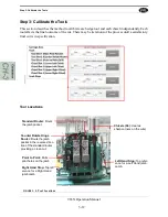
Page 44: ...reen includes access to the most commonly used controls of the Machine For information see About the Main Control Screen on page 2 15 Manual Servo Con trol Operates the machine manually by moving the servo motors For information see About the Manual Servo Control Screen on page 2 28 Tool Config For information see About the Tool Config Tabs on page 2 29 Calibration Refine and calibrate servo drive...

Page 45: ... This section includes descriptions of the Main Control Screen Select the Main Control Tab The Main Control Screen is the most utilized screen Information to machine a jamb is displayed on this screen FIGURE 2 5 965X Main Screen Machine Controls See page 2 16 Job Parameters and Tasks See ...

Page 46: ...tion of the machine Desig Sections Description A Main Control Machine Control B Sequence Controls Controls of the process C In Position Clamps Displays the Location of Clamps used for the cutting process D Routine Speed Adjust the speed of the cutting process E Jamb Support Block From a drop down menu choose the correct Jamb Support Block ...

Page 47: ...Machine button This button will reset the machine to the start position Important Press the Home button after resetting the machine Setup Mode On Off Select Setup Mode to toggle on or off In the On mode a safe mode is active The machine will go through normal sequences except the cutting motors will be inactive Use this mode to check the machine operation without making a cut on the jamb With the ...

Page 48: ...y used Toggle Clamp Select the activate and deactivate Clamp Note The mechanical foot pedal button is most commonly used Next Group During processing a jamb additional setup may be required select the next Group Button to continue processing Groups are indicated on the main screen Grayed background of the Task Box indicates that no processing is done Jamb End Dado Reference Select to switch stop r...

Page 49: ...ected at the KvalCAM Door Job Library Activated Jamb Clamps are highlighted in a orange background Jamb Clamp Location Note The Jamb Clamps can be toggled by selecting the Clamp button If needed may be used to position the jamb About Speed Control Adjust the speed of the cut Press the graduated speeds or select box or enter a desired speed The speed can be changed during real time processing Jamb ...

Page 50: ...e drop down menu 2 Identify matching Jamb Support Block Blocks are marked with identification num ber 3 If changing the blocks remove the existing blocks replace with the correct ones 4 Add the new blocks 10 onto the vertical stop assembly securing them by aligning the pins to the jamb stop About the Jamb Support Blocks Add the designated Jamb Support Block See Figure 2 6 FIGURE 2 6 Add a Jamb Sup...

Page 51: ...hine feedback and controls section Desig Sections Description A Door Job Specs View Door Job info job name jamb parameters Group Cut Information A display the number of groups in the Door Job Task Message A display of the sequence of the jamb machining B Task Control Information A display of the Feature Group information ...

Page 52: ...layed Jamb Specs Specifications are set in the KvalCAM Door Job and displayed here Current Group Displays the current and number of groups in the job Note Groups are cutting routines that require a different setup within the job Status Message Displays the steps in the cutting process Follow the steps displayed in the message box during cutting the jamb ...

Page 53: ...utting of the shape Color coded icons to identify the type of cut A status box to display the action being performed Location of the cut either referenced from the Jamb Stop to the top of the cut or Jamb Stop to the center of the cut The extent of the cut length Roll over to display KvalCAM job parameters Task Display to Jamb Cut Example Relationship to the jamb cut and the task screen is displaye...

Page 54: ...ns on page 2 25 Cut Locations Displays the location of the cut The reference of displayed value can be changed Dado to top of cut Dado to center Jamb End to top Jamb End to center Task Enable Disable Select check box to enable or disable this task See About the Skip Cut Check Box on page 2 25 Timer Indicates the time to cut this task See About Timers on page 2 27 Extent Displays the parameter of t...

Page 55: ...rage shelf to catch the refuse About the Process Box Follow the cutting process by reading the text displayed in each Task Box Pending Waiting for process to begin Running Cutting is taking place the Clock also signify that the action is running Completed Cutting is completed for that shape Skipped See Figure 2 10 About the Skip Cut Check Box In an active group clear the Check Box to skip that cut...

Page 56: ...the edge of the jamb To toggle between jamb and dado select the Jamb Reference button in the Sequence menu The change will be reflected in the Task Box FIGURE 2 11 Jamb Reference About Rollover Parameter Information To display a pop up window with parameter summary of the cut roll over the upper left hand cor ner of the Task Box FIGURE 2 12 Roll Over Parameters Mouse Roll Over ...

Page 57: ... Operation Manual About Timers The Main screen contains timers that add up the time for each individual cuts and a timer that adds up the entire process FIGURE 2 13 Timers Total Time to complete the entire process Time to complete selected cut ...

Page 58: ...xis Head Movement Direction The illustration below shows the direction the head moves when the servos are controlled manu ally FIGURE 2 14 Movement Direction of Carriage Head Select the Manual Servo Control Screen Tab X Axis Forward Direction Push and hold the Forward Button to move carriage in this direction To go in the opposite direction push and hold the Reverse Button Z Axis Forward Direction...

Page 59: ...ered and saved to the database This information is valuable to compute and provide the most precise cut available The Tool Config Screen contains Access to tools Pop up menus to enter information about each tool Specifications Router or Drill The ability to enable or disable specific tool slots The ability to name the tools to familiar names The ability to lock and unlock the ability to enter data...

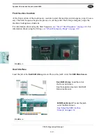
Page 60: ...e button after making changes to the Tool Configuration data If not selected the data will not be stored To Unlock 1 Select the Unlock Button 2 Enter Password in the Pop Up window 3 Click OK 4 The Unlock Button will change to a Lock Button 5 Tools can now be configured 6 Configure and Save the data To Lock Select the Lock Button and repeat instruction above About Using Tool Configuration 1 Identif...

Page 61: ...oose between entering router information or drill information Each tool can be enabled or disabled To Disable Select the Enabled Check Box A red line will cross out the tool on the list The tool slot menu will turn red The tool will not operate during the cutting pro cess To Enable Re select the Enabled Check Box ...

Page 62: ...calibrating or checking the wear of a tool Dis crepancies can be viewed before cutting into a jamb saving product and time The figure below displays a sample of a good Deep Mortise Cut 1 Load a Job from the KvalCAM Library into the Job Queue 2 Select the Tool Path Review Path tab Note There may be a delay before the routine starts 3 Select a G Code routine form the drop down menu 4 Select the Rend...

Page 63: ...iewing G Code To view a G Code file left click the Cutting Icon The file will open in a separate window Note On first use set the file to open in the desired application using the Open With function of Windows Notepad Notepad etc FIGURE 2 16 Opening G Code Left Click the Icon ...

Page 64: ...s Status includes a True flag if the assembly is in operation or a False flag if not in operation Also status can include data and motor states idle operation The data can be filtered to observe certain aspects of the operation of the machine This tool is great for troubleshooting to locate faulty assemblies FIGURE 2 17 Status Screen Filter Data Status is listed by Location List of Parameter of ja...

Page 65: ...e to machine sections or functions The top line will have the most current routine that is running The codes are color coded Red Error Green Report is a non issue Yellow Warning If the machine issue can not be resolved call Kval Inc 1 800 553 5825 Have any error code that is displayed ready to give the Kval representative This will aid in troubleshooting and shorten down time FIGURE 2 18 Log Scree...

Page 66: ...e Red Machine Error Solid General Error 1 Flash EtherCat Device not Ready to Run 2 Flashes VFD Servo or Motor Error 3 Flashes 24 VDC Power Error Yellow External Error Solid General Error 1 Flash 3 Phase Voltage Error 2 Flashes Low Air Error Blue Operator Status Solid Waiting for Operator 1 Flash Reposition Door Green Machine is Operational Safety OFF Clear Safety Project not Running Red Safety PLC...

Page 67: ... Summary Page About Calibration Descriptions of the Calibration Menus Tips to look for before calibrating page 3 2 About the Calibration Tabs Descriptions of the Calibration Tabs page 3 3 How to Enter Calibration Data Descriptions of how to use the calibration screens page 3 6 About the Calibration Screen Descriptions of the calibration available page 3 8 ...

Page 68: ...libration Reference Cut This chapter describes the Calibration Menus In the Calibration Menus offsets are entered to calibrate assemblies in the machine See About the Calibration Tabs on page 3 3 Before you Calibrate Before you start calibration check for the following common issues 1 Is the loaded setup correct for the current cut 2 Check tools for wear 3 Is the correct Calibration loaded 4 Are t...

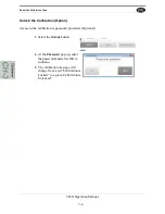
Page 69: ...Log Screens for error report ing Finding errors from these screens will help localize problem areas Note If the machine issues can not be resolved call Kval Inc 1 800 553 5825 Have any error code that is displayed ready to give the Kval representative This will aid in troubleshooting and shorten down time Access to the Calibration Adjustments Buttons to unlock access to calibration save a calibrat...

Page 70: ...ation Option Access to the calibration is password protected Optional 1 Select the Unlock button 2 At the Password pop up enter the password and select OK to continue 3 The calibration message will change from a red Calibration is Locked to a green Calibration is Unlocked ...

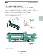
Page 71: ...mb cut second finger and thumb at right angle to each other The first finger rep resents the positive direction of the Z Axis the thumb represents the positive direction of the Y Axis then second finger represents the positive the direction of the X Axis FIGURE 3 2 Axis Direction X Axis Positive movement Z Axis Positive movement Y Axis Positive movement To understand the machine axis movement dire...

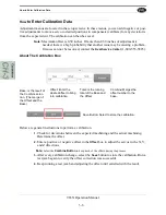
Page 72: ...to perform a calibration 1 Check for deviations between the expected machining and the actual machining Determine the offset 2 Enter a positive or negative offset in the Offset box to adjust the servos in the X Y and Z directions Note Select the Combine Button to keep track of the offsets during the process 3 After every calibration change select the Save button to store the calibration Run a test...

Page 73: ...a Restore Point 1 Select the Restore Points button 2 Select the Save Current button from the pop up win dow save current calibration 3 Name and enter to save To Load or Delete a Restore Point 1 Select the restore point from the menu 2 Select the Load button to use the calibration Select the Load button to load 3 Select the Delete button to delete the point ...

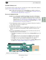
Page 74: ...ording to How to Enter Calibration Data on page 3 6 Ensure Calibration is unlocked 965X Calibration Screen Calibration Selections The table below describes the available calibration routine Calibration Adjustments Performed Carriage Axes No Access Tools Adjust each Tool Slot X Y Z axis and tool diameter offsets Adjust each Chisel offset Stops Adjust the Right Hand jamb Stop offset X axis Adjust th...

Page 75: ...of calibration For directions on how to use the configuration menus See About the Tool Config Tabs on page 2 29 To help identify tools that need to be calibrated view Tool Path Review See About the Tool Path Preview Test Screen on page 2 32 Important It is crucial to calibrate or verify the settings in the order described in this section If the steps are not followed in the correct order all calib...

Page 76: ...If the measurements of this check are out of specification contact the Kval Service Department to check the adjustments Procedure 1 Home the machine 2 Measure the distance between the Edge of Carriage Plate to the Edge of the Machine See Figure 3 3 3 Verify that the distance is 5 0 inches 0 005 inches Important If the measurement is outside the specification Do not operate the machine Stop and con...

Page 77: ...e cut has been made check the location and shape of the cut See Figure 3 4 5 Perform the Left Hand Rule from the rear of the machine to determine axis direction See illustration below If the location is out of specification in the length of the jamb edge the X Axis needs to be adjusted If the location is out of specification in the width of the jamb edge the Y Axis needs to be adjusted If the plun...

Page 78: ...ss until a satisfactory final cut is in specification Tool Locations FIGURE 3 5 Tool Locations Left Hand Stop Top refer ence for a Left Hand jamb Jamb Right Hand Stop Top ref erence for a Right Hand jamb Jamb Point to Point Drills pilot holes on the jamb Counter Rotate Hinge Router Routs the jamb pocket in the reverse direc tion of the standard router providing a clean cut Standard Router Routs th...

Page 79: ...eview See About the Tool Path Preview Test Screen on page 2 32 1 Create a Door Job of a Cut of your choice The example in this section is a jamb cut with a plunge and lock plate at a depth of 0 25 2 Add Door Job to the Queue 3 Once the cut is machined measure the length width and depth positions of the cut If the cut is not in the specification determine which tool and axis needs to be cali brated...

Page 80: ...ate and Standard Router not aligned Check router cut diameter See Routers How to Isolate and Calibrate a Specific Router on page 3 18 Check the Tool Path Review page to isolate routers Use Tool Config to turn routers on or off to isolate See Routers How to Isolate and Calibrate a Specific Router on page 3 18 FIGURE 3 7 Example of Axis Movement Direction X Y Z Y Z X ...

Page 81: ... cut In the case below the Lock Plate shape is longer in the Positive X axis Enter a the measured difference negative value in the Offset Box to bring into specification Depth of Rectangle Cut The Rectangle is shown looking down the top edge of the jamb The actual cut deeper than the expected cut and is out of calibration in the Z Axis Using Figure 3 6 and Figure 3 7 as a reference enter the measu...

Page 82: ...bration data see How to Enter Calibration Data on page 3 6 1 Create a Door Job of a cut of your choice with a depth that does not go through the jamb The example in used in this section is a Jamb Lock Cut 2 Add Door Job to the Queue 3 Once the cut is machined check the corners of the cut If the corners are not in the specifications find which corner needs to be calibrated 4 Perform the Left Hand R...

Page 83: ...n and shape of the chisel cuts figure shows the chisel locations Look for stair step cut at the corners Check depth of the corner cuts Use Tool Config to turn chisels on or off to isolate FIGURE 3 10 Chisel Locations Figure 3 11 shows the direction of the axis for each chisel location FIGURE 3 11 Chisel Reference Axis Direction Upper Min Chisel Lower Min Chisel Lower Max Chisel Upper Max Chisel Lo...

Page 84: ...to disable all tools except the router to be verified 2 Create a Door Job that has a rectangle with Width 1 5 Nominal Tool Diameter For Example If it is a 1 0 inch diameter router then set the Width 1 5 1 0 1 5 3 Set the Length large enough for the tool to fit in the Cut For Example If it is a 1 0 inch diameter router then set the Width 2 0 1 0 1 0 4 Set the depth deep enough to measure For Exampl...

Page 85: ... the tool diameter calibration 1 5 1 6 2 0 05 If 1 45 is measured then adjust the tool diameter 1 5 1 45 2 0 025 2 Rerun the rectangle at another location and repeat the step above until there is no measurable difference between the input width and measured width of the rectangle 3 During this process measure the depth to calibrate the Z axis of the tool 4 Once the tool Diameter and Z axis calibra...

Page 86: ...ow to Isolate and Calibrate a Specific Router 3 20 965X Operation Manual Appendix Servo Motor Drive Assemblies FIGURE 3 13 Location of Servo Drive Motors X Axis Servo Motor Z Axis Servo Motor Y Axis Servo Motor ...

Page 87: ...age Head Descriptions of the tools located on the Carrage Head page 4 6 965X Jamb Clamps Description of the Jamb Clamp System page 4 8 About the Jamb Support Blocks Description of the Jamb Support selection and placement page 4 9 About Sensor Locations Sensor Locations on the machine page 4 11 About Servo Motors and Valve Banks Location of the Servo Motors and the Valve Banks page 4 13 About the E...

Page 88: ...amb in a repeatable reference to process the jamb Also includes the Reference Blocks on the Vertical Clamp See Assemblies on the Carriage Head on page 4 6 Operator Station The Operator s Station includes a touch screen keyboard to run the program that operates the Contains mechanical Machine Controls See Operator s Station and Controls on the 965X on page 4 3 Foot Pedal Controls Jamb Clamp Jamb St...

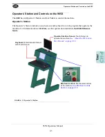
Page 89: ...touch screen and keyboard to run the program that operates the machine For information about KvalCam see the separate documentation KvalCAM Reference Guide FIGURE 4 2 Operator s Station Keyboard Enter data and interact with Touch Screen Machine Controls Mechanical controls of the machine See Machine Controls Section on page 2 16 Operator Interface Screen Touch Screen to operate the machine See Abo...

Page 90: ...tuations For information about using the Start Sequence see Step 7 Start Sequence on page 2 8 For information about using the E Stop see About Emergency Stops on page 2 12 FIGURE 4 3 User Interface Load the job at the KvalCAM Library screen Process the jamb cut at the 965X Main Screen FIGURE 4 4 KvalCAM Library Load the Job at the Door Job Screen See the separate document KvalCAM Reference Manual ...

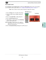
Page 91: ...oftware buttons the Operator s Station 1 Press the Stop pedal to extend the Jamb Stops 2 Align the jamb to Stop and Horizontal Jamb Clamps 3 Press to the Jamb Clamp to clamp the jamb 4 Press the Start Sequence pedal 5 After cutting is completed press the Stop Clamp pedal to unclamp the jamb Note Depending on instructions at the interface reposition the for a next cut or get the jamb ready for next...

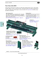
Page 92: ...ndles are attached to each Jamb Stop Occasionally the Head may need to be adjusted manually to align to the Dado or top of the jamb Access Cover Remove to access the Carriage Head tools Note Always Lockout Tagout if accessing the tools Left Hand Stop Top refer ence for a Left Hand jamb Jamb Right Hand Stop Top ref erence for a Right Hand jamb Jamb Point to Point Drills pilot holes on the jamb Coun...

Page 93: ...ylinders FIGURE 4 7 Servo Axis Direction The axis directions are defined in the illustration below FIGURE 4 8 X Axis Servo Motor Z Axis Servo Motor Y Axis Servo Motor Chisel Cylinders Standard Router Cylinder CCW Router Cylinder Predrill Cylinder X Axis horizontal across the machine Y Axis horizontal forward and back Z Axis vertical into cut and away from cut ...

Page 94: ... For more information about the interface see About the 965X interface Screens on page 2 14 r FIGURE 4 9 Jamb Clamp Assembly Detail The figure below describes the parts of the Jamb Clamp assembly FIGURE 4 10 Jamb Clamps and associated numbering at the display Vertical Clamps After jamb is set into position the clamps extends up to secure the jamb Clamp Clamp Horizontal Clamps After jamb is set int...

Page 95: ...valCAM Blocks are held into place by pins lift up remove and replace with desired blocks Note Be careful in handling the blocks They are used as a flat machined reference for the jamb Any dents or nicks may cause a change in reference If needed blocks can be ordered through the Kval Parts Store FIGURE 4 11 Jamb Support Block Storage The blocks are stored to custom fit at each end at the machine Th...

Page 96: ... to the receiver The receivers have a match ing row of synchronized photo detectors that read the signal from the emitter Important The system is aligned by trained technicians Do not move the emitter or receiver modules This may cause misalignment if the system is mis aligned the machine will not start FIGURE 4 13 Light Curtain Location If the Beam is Broken If the beam is broken during the cutti...

Page 97: ...nsors on the machine Photo Electronic and Inductive Proximity Sensor FIGURE 4 14 Examples of Sensor Sensor Locations on Machine Sensors that are located on Frame and the Carriage Head the machine are identified in the illustra tions below and on the next page See the machine E Print for more information about the sen sors Frame Sensors FIGURE 4 15 Frame Sensor Locations Photo Eye Detector Emitter ...

Page 98: ...igure below shows the locations of the sensors location on the Carriage Head In addition to crash sensors the Carriage Head homing sensor is also present FIGURE 4 16 Carriage Head Sensor Locations Homing Sensor Z Axis Crash Sensor Y Axis Crash Sensor X Axis Crash Sensor ...

Page 99: ...tions Figure 4 17 shows the locations of the valve banks on the machine The valve banks include con trol valves solenoids that drive cylinders to move different loads in the machine The solenoid if controlled by the PLC by applying a high voltage or a low voltage to a control coil Controls for example are extending and retracting router drill clamping a jamb Note For detailed information about the...

Page 100: ... section is an overview of the electri cal components Refer the machine s electrical prints for in depth information 965X Main E Panel The Main Electrical Panel Supplies voltages to the machine Contains the PLC Programmable Logic Controller Contains servo drives to interact with the servo motors VFDs Drives the tool motors FIGURE 4 18 Main Panel PLC 965X 24 VDC and 110 VAC Terminals Relays 24V DC ...

Page 101: ...C and power connec tions For example jamb sensors width adjusts and tool interfaces FIGURE 4 19 Sample of a Frame Node Typical Block Diagram of Network Connections FIGURE 4 20 Block Diagram of Network Connections PLC Interface Top Ethernet cable is PLC Bottom Ethernet goes to Carriage Node Inputs and Outputs Interconnect Bar ...

Page 102: ...ons and Power Distribution FIGURE 4 21 Location of Nodes on the 965X Power Network Connection Frame Node Main E Box Contains Servo Drives Network Connec tions power and Inputs Outputs originate this box and are connected to Nodes Power Dis tributed to Points in the machine ...

Page 103: ......
Page 104: ...partment Kval Incorporated 825 Petaluma Boulevard South Petaluma CA 94952 Contacting KVAL Phone and Fax In the U S and Canada call 800 553 5825 or fax 707 762 0485 Outside the U S and Canada call 707 762 7367 or fax 707 762 0485 Email service kvalinc com http www kvalinc com ...

Reviews: