About Switches and Sensors
4-23
965X Service Manual
.
Using Sensors to Trouble Shoot
• Photo Sensors often get dirty. Make sure they are clean. If they are not clean, debris
may block the signal or provide a false signal.
• Check output voltages of the sensors in the
active
mode. The voltage should effec
-
tively equal
0 VDC
• Check the output voltages of the sensors in
inactive
mode.The voltage should effec
-
tively equal
24 VDC
Note:
The distance from an eye to the door should be in range. Typically the range
should be 3/4'' to 7/8'' from the top of all eyes to the door.
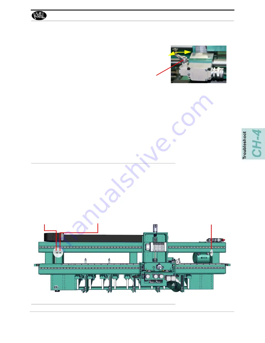
FIGURE 4-42.
Examples of Sensor
Sensor Locations on Machine
Sensors that are located on
Frame
and the
Cutter Head
the machine are identified in the illustra
-
tions below and on the next page. See the machine E-Print for more information about the sen
-
sors.
Frame Sensors
FIGURE 4-43.
Frame Sensor Locations
The L
imit Switch
is activated by an assembly moving a switch arm.
• .Depending on the model of limit switch, the
amount of “pre-travel” (amount of movement from
the arms resting position) is either 5 or 20 degrees
before the limit switch actuates (Clicks).
Switch Arm
Homing Sensor
Crash Sensor
Crash Sensor


