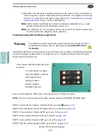
About Typical VFD Motor Drive Control
KVAL 990-F4 Service Manual
4-12
About Typical VFD Motor Drive Control
An adjustable-speed drive is used to control the motor speed and torque by varying motor input
frequency and voltage. A variable-frequency drive (VFD) is used in
KVAL
machinery to accu
-
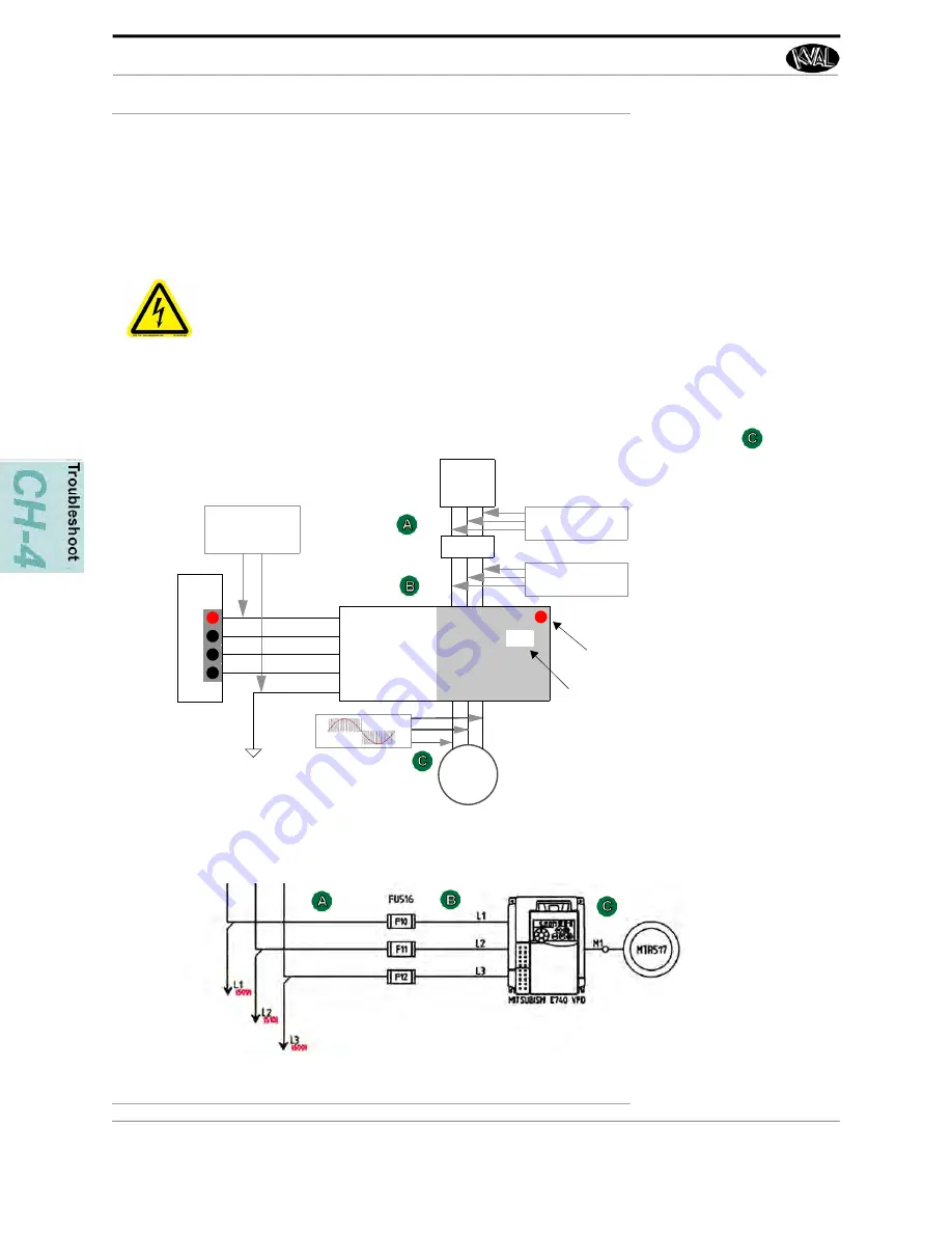
rately drive motors for machining or moving product through the machine. The figure below
shows a block diagram of a typical motor drive circuit.
FIGURE 4- 3.
Block Diagram of a Common Drive Control
High Voltage may cause personnel
injury or death.
Troubleshooting checks
must
be performed by a Qualified Electrical Technician
.
Common Motor Drive Control:
PLC
Output
Fuse(s)
Line
Voltage
Motor
(Power)
Motor
Power
Input
Output
Power
Control Circuit
Common
ON
Measure
Control Voltage
-24 VDC here
Measure
Line Voltage here
Measure
Line Voltage here
ON
Drive
STF (Forward)
RL
STR (Revers 2)
SD (COMMON)
OFF
OFF
OFF
Run
300
Run Light
should be ON
Displays the
Motor Frequency
15 to 300 Mhz
Schematic Drawing of VFD
Note: T
he output to
motor “C” contains
pulse signals at
varying frequencies.
A DMM may not be
able to measure the
frequency and the
pulse rate.
Use the VFD inter
-
face to check, cur
-
rent, voltage and
frequency.


