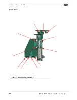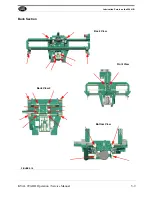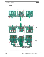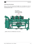
Mechanical set up of the 990-HB
5-18
KVAL 990-HB Operation / Service Manual
3.
Turn on the control transformer and press the start machine button, push the start
sequence button at the operators panel
4.
Lock bore and router should come up at the same time, and move through their
respective motions
5.
Lock bore lowers and router shifts out.
6.
Bolt drill will then move inward.
Check to ensure the cycle performs as previously stated. Look for sticking or uneven
movement of each assembly. Look for physical obstructions interfering with proper
movement of the assemblies.
Once the back section is running smoothly, stop operation and replace the two drill bits
into the respective collects; turn on and push in the plate router using the Acuflex
wrench. Use a cull door you can ruin and make a practice cut following the next few
steps.
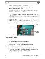
After the bits have been installed, install a new chip-out by removing the two 1-inch
collars in front of the chip-out housing. Then you can slide the whole assembly off to
expose the old chip-out for easy replacement. There are four ¼-inch flat head bolts
that hold the two plates that hold the chip-out in place. By loosening all four bolts on
the plate you can remove the old chip-out and replace it with a new one. Make sure
that the chip-out is even when placed in position, and that all four bolts are tightly fas-
tened. It should be hanging lower than the surrounding metal plates. It is critical that
the chip-out is tight and flush with the tow brackets; otherwise the chip-out can vibrate
loose.
1.
Load the door into the machine.
2.
Clamp the door in place using the “Door Clamp” foot pedal.
* Be careful to avoid the pinch points such as between the hinge router faces, H-
blocks, door edges, etc.…
3.
Press the “Burn Chipout” button on the manual run touchscreen. The “burn chip-
out” mechanism is only active when this button is held down, similar to the trigger
of a power drill: when it is released, the action halts. This allows the operator to
burn the chip-out in controllable increments. Activate the chip-out bore by tapping
the button, listening until you hear the bore emerge on the other side of the chip-out
block.
Note:
Pressing the “Door Clamp” foot pedal should bring in the back section and pivot
down the jamb clamps.
Setting Up Lock Height
Now that the hinges are in there right places, and your door stops have been set, you
can adjust the lock section to put the lock in the right place, relative to the door stop.
NOTE:
Check door to make sure it is square. It is important that you set the lock
height with a good door. Check the door for square by measuring the door diagonally
point to point, and again from opposite points (measure an “X” across the door). If
both measurements are the same, the door is square and good to go for set-up.
Summary of Contents for 990-HB
Page 4: ...KVAL 990 HB Operation Manual ...
Page 25: ...Safety Sign Off Sheet 1 17 KVAL 990 HB Operation Service Manual ...
Page 26: ...Safety Sign Off Sheet 1 18 KVAL 990 HB Operation Service Manual ...
Page 66: ...Diagnostic Screen 2 40 KVAL 990 HB Operation Service Manual ...
Page 84: ...Calibration of the Back Section 3 18 KVAL 990 HB Operation Service Manual ...
Page 88: ...System IT Administration 4 4 KVAL 990 HB Operation Service Manual ...


