About Sensors
6-3
KVAL 990-HB Operation / Service Manual
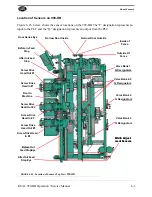
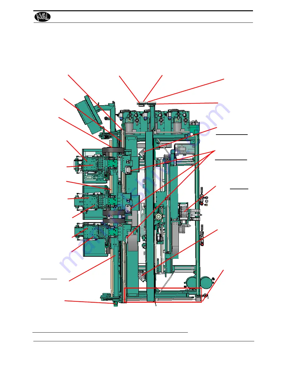
Location of Sensors on 990-HB
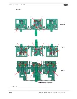
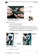
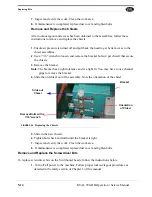
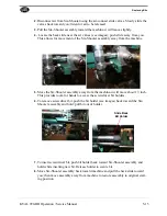
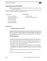
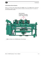
Figure 6- 26 below, shows the sensor locations on the 990-HB The “I” designation represents an
input to the PLC and the “Q” designation represents an output from the PLC.
Inside of
Fence
Outside Of
Fence
Narrow Door Outside
Narrow Door Inside
Door Sense Eye
Before In-Feed
Stop
Screw Drive
Head Out #1
Door In
Machine
After Out Feed
Stop Eye
After In-Feed
Stop
Screw Drive
Head Out #2
Screw Drive
Head In #2
Screw Drive Head
In #3
Screw Drive
Head In #1
Screw Drive
Head Out #3
Width Adjust-
ment Sensors
Valve Bank 1
Q Designators
Width Adjust-
ment Sensors
Valve Bank 2
Q Designators
Valve Bank 3
Q Designators
Before Out
Feed Stop Eye
Valve Bank 4-5
Q Designators
FIGURE 6- 26.
Location of Sensors Top View 990-HB
Summary of Contents for 990-HB
Page 4: ...KVAL 990 HB Operation Manual ...
Page 25: ...Safety Sign Off Sheet 1 17 KVAL 990 HB Operation Service Manual ...
Page 26: ...Safety Sign Off Sheet 1 18 KVAL 990 HB Operation Service Manual ...
Page 66: ...Diagnostic Screen 2 40 KVAL 990 HB Operation Service Manual ...
Page 84: ...Calibration of the Back Section 3 18 KVAL 990 HB Operation Service Manual ...
Page 88: ...System IT Administration 4 4 KVAL 990 HB Operation Service Manual ...

