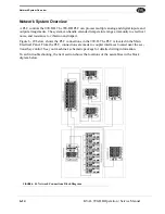
Network System Overview
6-15
KVAL 990-HB Operation / Service Manual
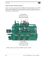
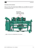
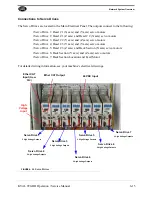
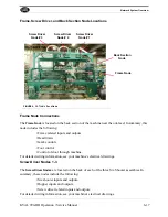
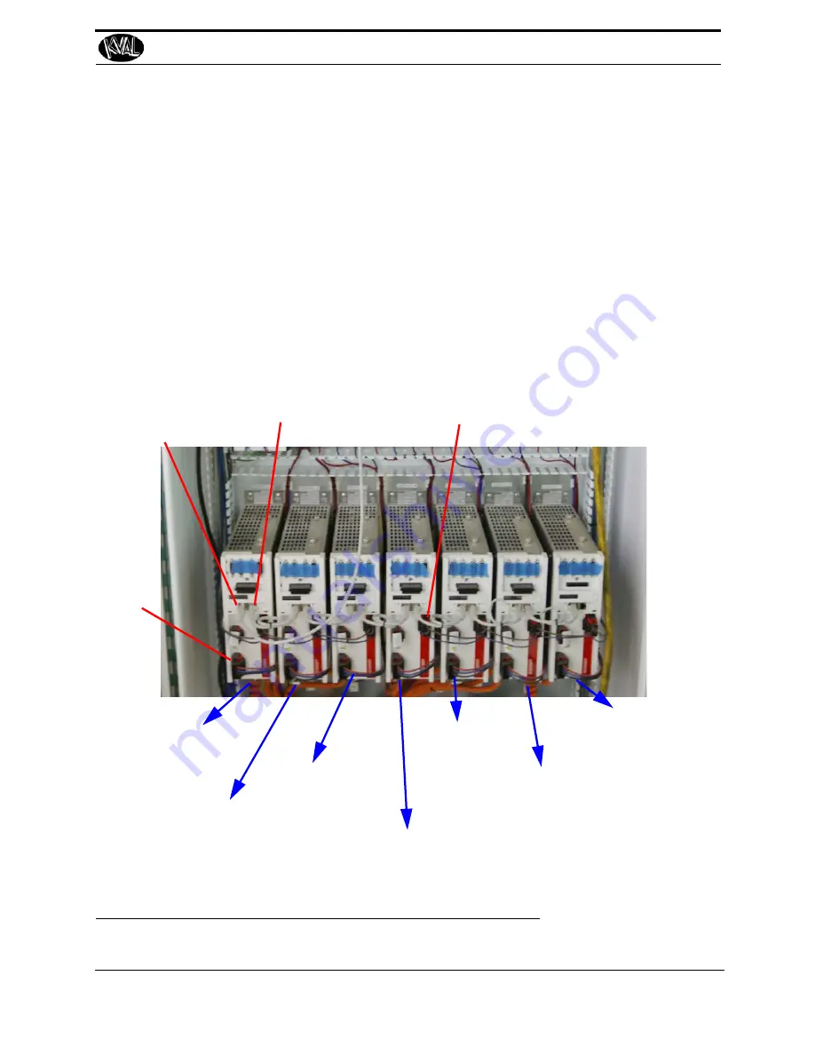
Connections to Servo Drives
The Servo Drives are located in the Main Electrical Panel. The outputs connect to the following:
• Servo Drive 1: Head # 1 (X axis) and (Y axis) servo motors
• Servo Drive 2: Head # 1 (Z axis) and Head # 2 (X axis) servo motors
• Servo Drive 3: Head # 2 (Y axis) and (Z axis) servo motors
• Servo Drive 4: Head # 3 (Y axis) and (Y axis) servo motors
• Servo Drive 5: Head # 3 (Z axis) and Back Section (X axis) servo motors
• Servo Drive 6: Back Section (Y axis) and (Z axis) servo motors
• Servo Drive 7: Back Section Location and Feed Motor
For detailed wiring information, see your machine’s electrical drawings.
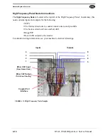
24 VDC Input
Ether CAT Output
Ether CAT
Input
(From
PLC)
High
Voltage
Input
Servo Drive 1
2 High Voltage Outputs
Servo Drive 2
2 High Voltage Outputs
Servo Drive 3
2 High Voltage Outputs
Servo Drive 4
2 High Voltage Outputs
Servo Drive 5
2 High Voltage Outputs
Servo Drive 6
2 High Voltage Outputs
Servo Drive 7
2 High Voltage Outputs
FIGURE 6- 30.
Servo Drives
Summary of Contents for 990-HB
Page 4: ...KVAL 990 HB Operation Manual ...
Page 25: ...Safety Sign Off Sheet 1 17 KVAL 990 HB Operation Service Manual ...
Page 26: ...Safety Sign Off Sheet 1 18 KVAL 990 HB Operation Service Manual ...
Page 66: ...Diagnostic Screen 2 40 KVAL 990 HB Operation Service Manual ...
Page 84: ...Calibration of the Back Section 3 18 KVAL 990 HB Operation Service Manual ...
Page 88: ...System IT Administration 4 4 KVAL 990 HB Operation Service Manual ...


