4
KVAL 990-HB Operation / Service Manual
troubleshooing
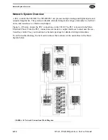
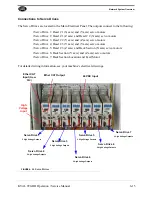
voltage levels
x-axis and y-axis locations
service
connecting your machine to KVAL Service
servo drives
connections
location in main electrical panel
servo positions
feedback
setup hinges
group location
setup screens
shut down system
description user interface
six light panel
description
sequence list
slot calibration routine
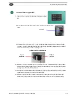
start light
description
start light description
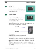
start machine button
power up
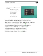
status light panel
description
use as troubleshooting key
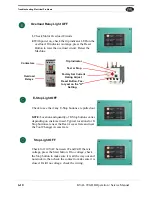
stop light description
stop sequence button
description user interface
strike plate
calibration
strike plate location
adjusting
T
tagout procedure
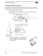
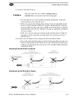
troubleshooting
air cylinders
using status lights
TwinCAT 2® software automation software
U
USB module
user interface screens
menu map
V
voltage levels
sensors
VTD
location in high frequency panel
W
width adjust
user interface description
Windows CE® operating system,about
X
X-axis
calibration routine
illustration of adjustment
Y
Y-axis
calibration hinges
illustration of calibration
Z
zerk fittings
locations
zero-energy start-up
clean up
inspect
Summary of Contents for 990-HB
Page 4: ...KVAL 990 HB Operation Manual ...
Page 25: ...Safety Sign Off Sheet 1 17 KVAL 990 HB Operation Service Manual ...
Page 26: ...Safety Sign Off Sheet 1 18 KVAL 990 HB Operation Service Manual ...
Page 66: ...Diagnostic Screen 2 40 KVAL 990 HB Operation Service Manual ...
Page 84: ...Calibration of the Back Section 3 18 KVAL 990 HB Operation Service Manual ...
Page 88: ...System IT Administration 4 4 KVAL 990 HB Operation Service Manual ...

