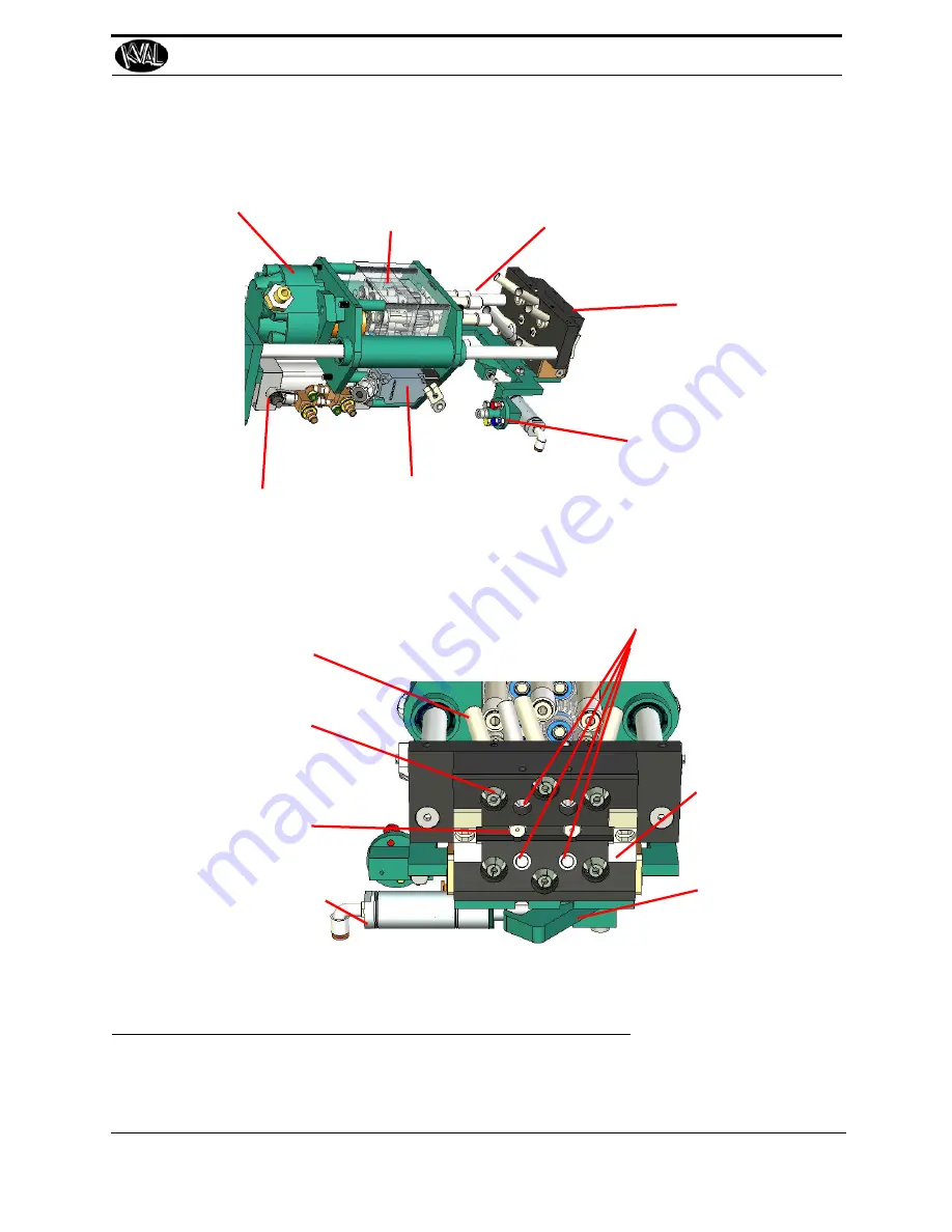
Split Shells X6:
Receives 6 screws, straight-
ens, and aligns them.
Hinge Indexer X2:
Factory set to align
hinge.
Magnets:
Four Magnets hold Hinge
for Application.
Index Spacers X2:
Factory set to align hinge.
Screw Receiver Tubes:
These tubes receive the
screws from the hopper by
way of plastic tubes
Latch Arm:
Latches to H Block
to secure in place.
Latch Arm Cylinder:
Moves latch arm in and out
of position
Air Motor
Gearbox:
Geared to drive 6
screws simultane-
ously
Chucks X6:
Holds 6 screws
aligned to the Door
and the Jamb.
Hinge Applicator:
Location to attach
Hinge
Turret to Adjust Depth:
Adjustable stops to set
the depth of the screw
drivers. Used with the
Forward Limit Switch.
*
Forward Stop
Limit Switch
*
Reverse Stop Limit on
other side
Plunge Cylinder:
Moves the screw
drivers into place
Operator’s Tour
2-9
KVAL 990-HB Operation / Service Manual
FIGURE 2- 7.
Six Shooter and Gear Box Call-Outs
Summary of Contents for 990-HB
Page 4: ...KVAL 990 HB Operation Manual ...
Page 25: ...Safety Sign Off Sheet 1 17 KVAL 990 HB Operation Service Manual ...
Page 26: ...Safety Sign Off Sheet 1 18 KVAL 990 HB Operation Service Manual ...
Page 66: ...Diagnostic Screen 2 40 KVAL 990 HB Operation Service Manual ...
Page 84: ...Calibration of the Back Section 3 18 KVAL 990 HB Operation Service Manual ...
Page 88: ...System IT Administration 4 4 KVAL 990 HB Operation Service Manual ...


