Operator’s Tour
2-14
KVAL 990-HB Operation / Service Manual
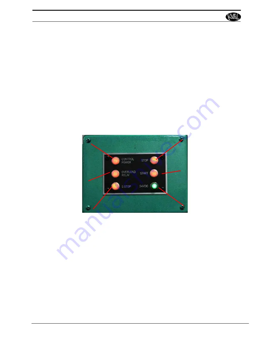
Description of the Six Light Panel
The six lights on this panel indicate the status of the 990-HB system.
The Sequence that the lights activate is as follows:
1.
Control Power
2.
Overload Relay
3.
E-Stop
4.
Stop
5.
Start
6.
24VDC
Control Power –
light
illuminates when the
Control Transformer
is pulled out and the
power is working on
secondary side-of
transformer
Overload Relay –
The overload circuit is
working when light is
on
E-Stop –
The back
gate is closed and Frame E-stop is not acti-
vated when this light is on.
24VDC –
light
comes on once the
ACR is latch and the
24VDC power Supply
is working
Stop –
This light will
be on if Machine
Stop button is deac-
tivated.
Start – T
his light will
be on once the
Machine Start button
is pressed and the
ACR Relay is latched.
Summary of Contents for 990-HB
Page 4: ...KVAL 990 HB Operation Manual ...
Page 25: ...Safety Sign Off Sheet 1 17 KVAL 990 HB Operation Service Manual ...
Page 26: ...Safety Sign Off Sheet 1 18 KVAL 990 HB Operation Service Manual ...
Page 66: ...Diagnostic Screen 2 40 KVAL 990 HB Operation Service Manual ...
Page 84: ...Calibration of the Back Section 3 18 KVAL 990 HB Operation Service Manual ...
Page 88: ...System IT Administration 4 4 KVAL 990 HB Operation Service Manual ...


