


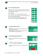
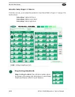
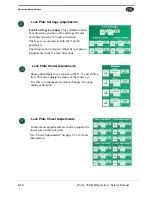


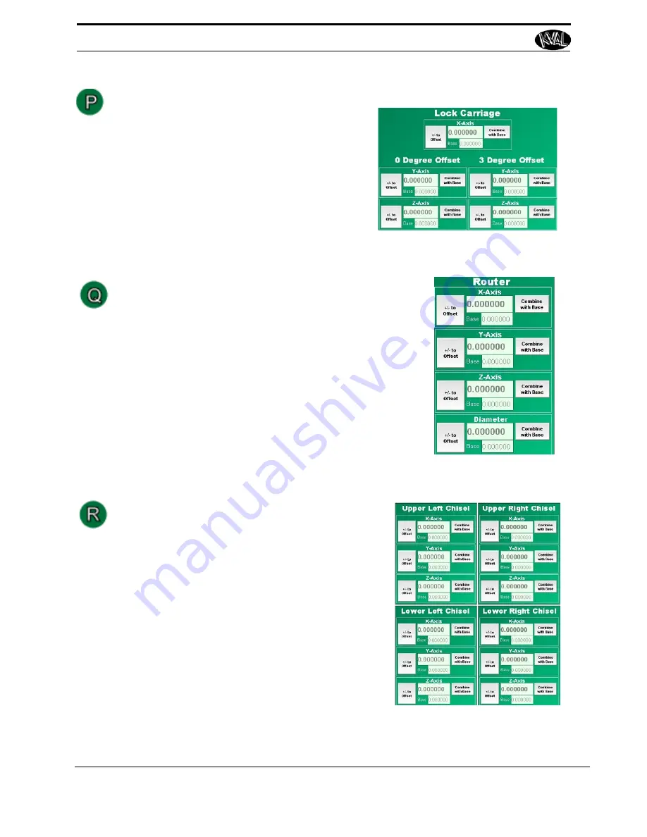
Lock Plate Carriage Adjustments
Lock Carriage Location:
This calibration num-
ber adjusts the position of the carriage (Router
and Chisels) in the X,Y,and Z direction.
The X axis is common to both the Y and Z
parameters.
The 0 degree and 3 degree offsets have separate
adjustments in the Y and Z directions.
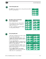
Lock Plate Router Adjustments
These adjustments move routers in the X, Y, and Z direc-
tion. This also adjusts the radius of the router cut.
Use this to compensate for minor changes in tooling
during calibration.
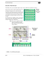
Lock Plate Chisel Adjustments
In this menu, adjustments are made to square the
chisel cuts on the lock plate.
See “Chisel Adjustments” on page 2-31 for more
information.
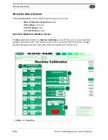
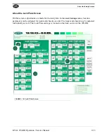
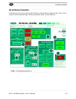
About the Setup Screens
2-34
KVAL 990-HB Operation / Service Manual
Summary of Contents for 990-HB
Page 4: ...KVAL 990 HB Operation Manual ...
Page 25: ...Safety Sign Off Sheet 1 17 KVAL 990 HB Operation Service Manual ...
Page 26: ...Safety Sign Off Sheet 1 18 KVAL 990 HB Operation Service Manual ...
Page 66: ...Diagnostic Screen 2 40 KVAL 990 HB Operation Service Manual ...
Page 84: ...Calibration of the Back Section 3 18 KVAL 990 HB Operation Service Manual ...
Page 88: ...System IT Administration 4 4 KVAL 990 HB Operation Service Manual ...


