Check Specifications of the Front Section
3-7
KVAL 990-HB Operation / Service Manual
Check Specifications of the Front Section
Follow these steps in this section to verify the result of the cut and, if necessary, adjust the
machine.
General Instructions to Adjust Parameters
From the Main Screen select
Setup
---
Setup Hinge 1. 2,
or
3
to get to the Hinge Setup screens.See
“About the Setup Hinges 1-3 Screens” on page 2-30 , for further detail.
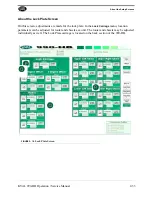
FIGURE3- 4.
Path to Setup Hinge Screens
Located in the setup screens are adjustment menus. In these menus you can add negative or posi-
tive adjustments to move a cutting assembly to the desired position. Enter the data in the white
box below the parameter. The
Base
display box keeps a running total of data entered to help keep
track of the changes. The
Combine with Base
button stores data in memory and should be used at
first to set a reference and at final to store data.
Title:
of assembly to adjust
Parameter:
to adjust (X,Y,and or Z
axis.)
Offset:
Select this button to add or
subtract the measured number
entered.
Base:
Keeps a Running Total of
measured numbers entered.
Enter:
Type in
measured
data
Combine Base:
Select this
button at
start
of adjustment
to set a reference and
end
of adjustment to store it.
FIGURE3- 5.
Sample of Adjustment Menu
Note:
KVAL suggests to follow the steps in the order below.
Step 1 Verify and Adjust the Hinge Carriage
Step 2 Verify and Adjust the Router Calibration
Step 3 Verify and Adjust the Pre-Drill Calibration
Step 4 Verify and Adjust the Chisel Calibration
Summary of Contents for 990-HB
Page 4: ...KVAL 990 HB Operation Manual ...
Page 25: ...Safety Sign Off Sheet 1 17 KVAL 990 HB Operation Service Manual ...
Page 26: ...Safety Sign Off Sheet 1 18 KVAL 990 HB Operation Service Manual ...
Page 66: ...Diagnostic Screen 2 40 KVAL 990 HB Operation Service Manual ...
Page 84: ...Calibration of the Back Section 3 18 KVAL 990 HB Operation Service Manual ...
Page 88: ...System IT Administration 4 4 KVAL 990 HB Operation Service Manual ...

