About Sensors
6-4
KVAL 990-HB Operation / Service Manual
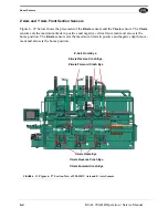
Z Axis and Y Axis Front Section Sensors
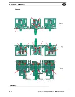
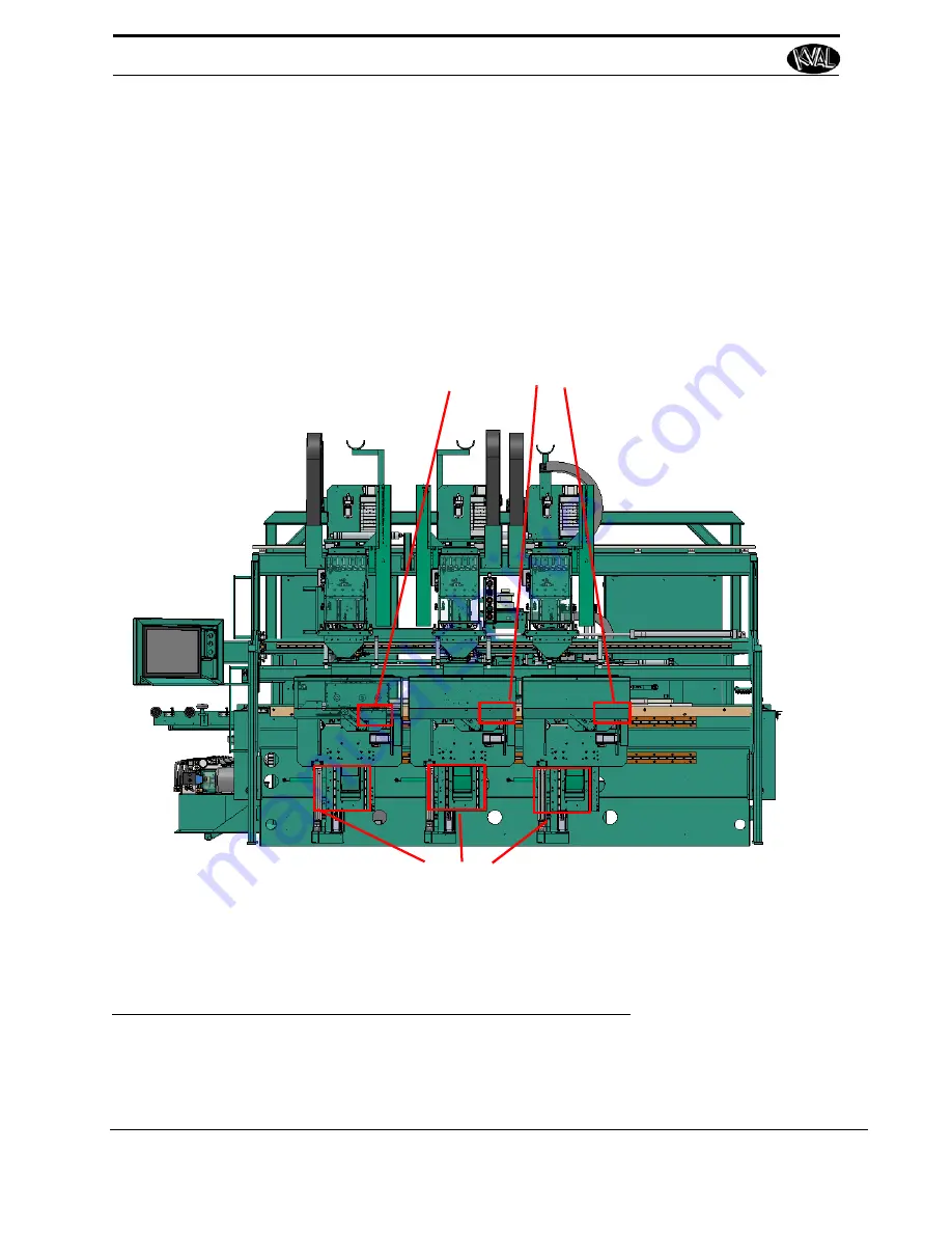
Figure 6- 27 below shows the placement of the
Z-Axis
sensors and the
Y-Axis
sensors. The
Y-Axis
sensors sets the maximum limits in positive and negative vertical movement and also sets the
home position. The
Z-Axis
sensors sets the maximum limits in positive and negative depth move-
ment and also sets the home position.
Hinge #1
Hinge #2
Hinge #3
Y-Axis Home Eye
Y-Axis Forward Crash Eye
Y-Axis Reverse Crash Eye
Z-Axis Home Eye
Z-Axis Forward Crash Eye
Z-Axis Reverse Crash Eye
FIGURE 6- 27.
Figure 6- 27 Section View of 990-HB Y Axis and Z-Axis Sensors
Summary of Contents for 990-HB
Page 4: ...KVAL 990 HB Operation Manual ...
Page 25: ...Safety Sign Off Sheet 1 17 KVAL 990 HB Operation Service Manual ...
Page 26: ...Safety Sign Off Sheet 1 18 KVAL 990 HB Operation Service Manual ...
Page 66: ...Diagnostic Screen 2 40 KVAL 990 HB Operation Service Manual ...
Page 84: ...Calibration of the Back Section 3 18 KVAL 990 HB Operation Service Manual ...
Page 88: ...System IT Administration 4 4 KVAL 990 HB Operation Service Manual ...

