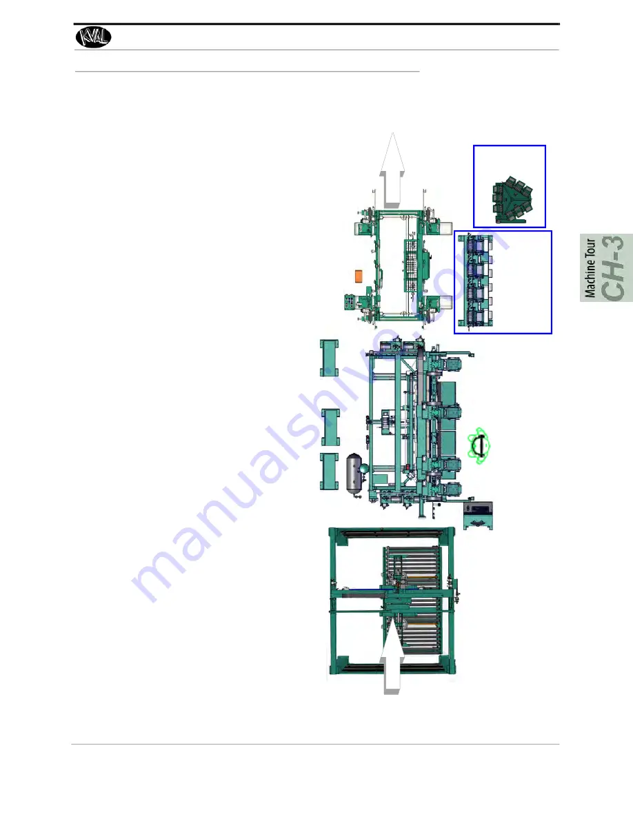
Common 990-FX Line Layout
3-3
KVAL 990-FX Operation Manual
Common 990-FX Line Layout
Below a common line layout of
990-FX
with an array hopper system.
The 990-FX:
• Cut a hinge pocket on a door and jamb for up
to three hinges (Head Assembly)
• Drill pilot holes for the hinge screws (Head
Assembly)
• Choose different screws by way of the Hop
-
pers. (Array, On Machine, or RTS-FX)
• Apply up to four hinges.(Six Shooter)
• Attach the hinges with screws (Six Shooter)
• Cut a lock and lock plate (Back Section)
• Is Controlled by a Central Operators Station
The Feeder:
• Automatically lifts a door from a stack in the
staging area
• The door is placed onto the powered roller
• )The door is fed into the
990-FX
automatically
or with a call door function.
• After the door is fed into the
990-FX
the action
is repeated
• For a detailed description of the Feeder, see
the Feeder Operation/Service Manual
Note:
Feeders may vary, common Feeders are the
ON-3 series the Handler series.
The 700 C:
• IA strike jamb and Header are placed into the
machine.
• A processed door is fed in from the
990-FX
• The door with the hinge jamb is gently lowered
into place.
• The door, header and strike jambs are clamped
by way to a foot pedal
• The foot pedal activates programed staple pat
-
terns to attach the jambs to the header.
• The door is fed out for packaging for packaging
• For a detailed description of the 700-C, see the
700-C Reference Manual
Door Path
RTS-FX
Hoppers
Array
Hoppers


