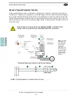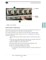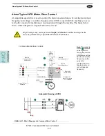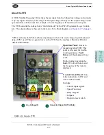
About Motion Control
4-3
KVAL Commander III Service Manual
Basic Control Circuit
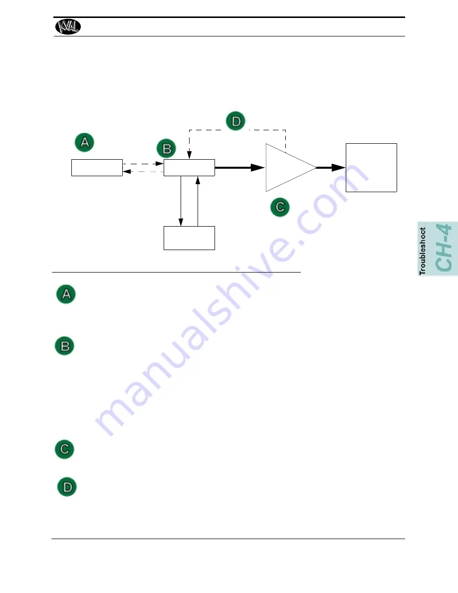
This section describes a basic control circuit. The Figure below shows a block diagram of a com-
mon control circuit. There are four parts to a motion control system:
FIGURE 4-24.
Block Diagram of Basic Motion Control
The Controller:
• Translates entered information into a form the positioning system can understand.
• Listens to the machine’s other subsystems waiting for the OK to move command.
• Sends the positioning instructions to the positioning system.
• Listens to the positioning system for position status (if there is a feedback loop).
• Tells the machine’s other subsystems when the move process is completed.
Examples: A PLC or a dedicated motion control board.
Positioning System:
• Moves the load.
Examples: A motor or a pneumatic cylinder.
The Position Feedback.
• Provides location information to the controller.
Examples: A limit switch, a photo eye, or ferrous eye, a resolver or an encoder
The User Interface:
• Allows communication between the humans and the machine.
Examples: A touch screen, a PC or a button panel.
Load
User Interface
Force
Positioning
System
Translated
Positioning
Controller
Instructions
Positioning
Instructions
(Optional)
Position Feedback
(Optional)
Machine’s Other
Subsystems
OK to move
Complete
Process
Summary of Contents for Commander III
Page 5: ...KVAL Commander III Service Manual KVAL Commander III Service Manual ...
Page 10: ...Notes ...
Page 31: ...Safety Sign Off Sheet 1 21 KVAL Commander III Service Manual ...
Page 36: ...Notes ...
Page 75: ...Collet Torque Values 3 39 KVAL Commander III Service Manual ...
Page 76: ...Collet Torque Values KVAL Commander III Service Manual 3 40 ...
Page 100: ...Network System Overview KVAL Commander III Service Manual 4 24 ...
Page 103: ......


