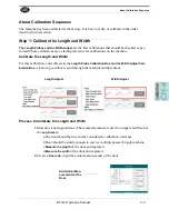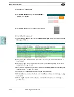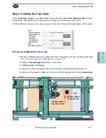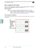
How to Enter Calibration Data
KVAL Operation Manual
4-6
How to Enter Calibration Data
Adjustment menus are located in the setup screens. In these menus, you can add negative or posi-
tive adjustments to move a servo to desired positions to compensate (calibrate) for any deviation’s
from the expected cut. The calibration can then be saved.
Note:
Maximum offset is 0.50 inches. If more than 0.50 inches of adjustment is
needed, there is a high probability that another issue may be causing a problem.
If issues can not be resolved, contact the KVAL Service Center KVAL Inc. (1-
800-553-5825).
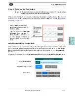
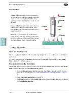
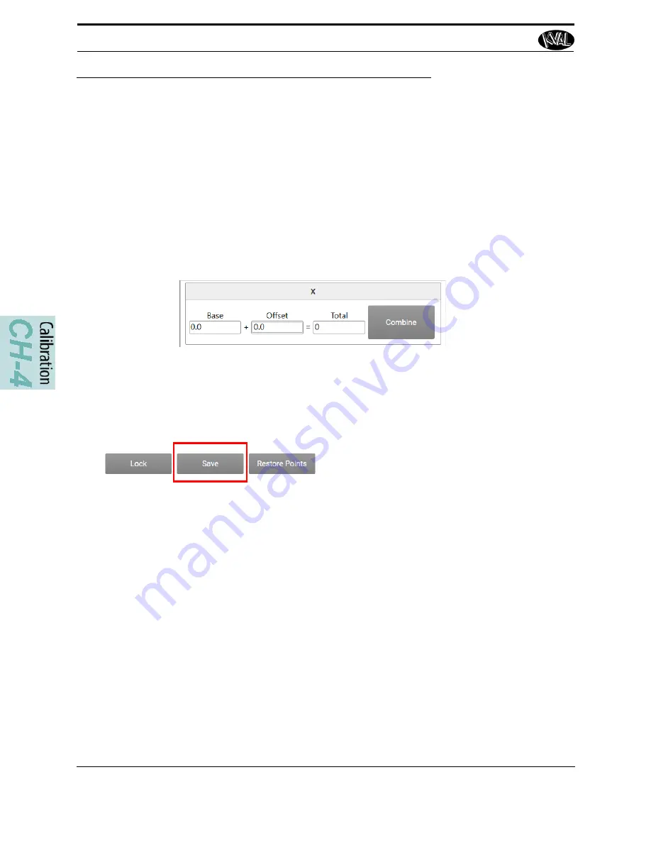
About The Calibration Box
Total:
Is the running
total of the
Base
and
the
Offset
Combine:
Merges
the offset number to
the base.
Base:
Is the result of
the
Combine
selec-
tion. (The merge of
the Offset and the
Base)
Offset:
Enter the
desired offset to bring
into calibration.
Save Button:
Select to store the calibration.
Below are general instructions to perform a calibration.
1.
Check for deviations between the expected machining and the actual machining.
Determine the offset.
2.
Enter a positive or negative offset in the
Offset
box to adjust the servos in the X, Y,
and Z directions.
Note:
Select the
Combine Button
to keep track of the offsets during the process.
3.
After every calibration change, select the
Save
button to store the calibration. Run a
test door again to verify the offset correction was successful.
4.
Keep running a test door and adjusting the offset until satisfied with the result.
Summary of Contents for DL-NCD
Page 10: ...KVAL DL NCD Operation Manual Table of Contents ...
Page 28: ...How to Download the Service Application KVAL Operation Manual 1 18 ...
Page 30: ...Safety Sign Off Sheet KVAL Operation Manual 1 20 ...
Page 62: ...About the LiteCutout Feature Detail KVAL Operation Manual 2 32 ...
Page 94: ...Appendix About Backing up the Data KVAL Operation Manual 3 32 ...
Page 118: ...Appendix Servo Motor Drive Assembly Locations KVAL Operation Manual 4 24 ...
Page 139: ...About the Electrical Panels KVAL Operation Manual 5 21 I ...
Page 142: ......
Page 143: ......


