Around the Machine
KVAL Operation Manual
5-7
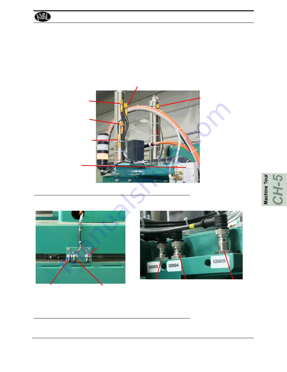
Homing and Limit Sensors
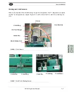
Refer to the machine’s Electrical Drawing for specific designators. The “I” designators are inputs
and the “Q” designators are outputs. Figures 5-3 and 5-4 show the X,Y, and Z Axis homing sen-
sors.
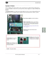
Z-Limit Neg
Z Home
Z-In Tool Changer
Z-Limit Pos
Dust Hood Up
Motor Release Tool
FIGURE 6.
Z Axis Sensors
Y Limit Pos
Y Limit Neg
Y Limit Home
X Limit Pos
X Limit Neg
I-2002
(X Home)
FIGURE 7.
X and Y Axis Homing Sensors.
Summary of Contents for DL-NCD
Page 10: ...KVAL DL NCD Operation Manual Table of Contents ...
Page 28: ...How to Download the Service Application KVAL Operation Manual 1 18 ...
Page 30: ...Safety Sign Off Sheet KVAL Operation Manual 1 20 ...
Page 62: ...About the LiteCutout Feature Detail KVAL Operation Manual 2 32 ...
Page 94: ...Appendix About Backing up the Data KVAL Operation Manual 3 32 ...
Page 118: ...Appendix Servo Motor Drive Assembly Locations KVAL Operation Manual 4 24 ...
Page 139: ...About the Electrical Panels KVAL Operation Manual 5 21 I ...
Page 142: ......
Page 143: ......

