Basic Control Circuit
6-6
KVAL Operation/Service Manual
Basic Control Circuit
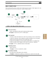
This section describes a basic control circuit. The Figure below shows a block diagram of a com-
mon control circuit. There are four parts to a motion control system:
Load
User Interface
Force
Positioning
System
Translated
Positioning
Controller
Instructions
Positioning
Instructions
(Optional)
Position Feedback
(Optional)
Machine’s Other
Subsystems
OK to move
Complete
Process
FIGURE 6-19.
Block Diagram of Basic Motion Control
The User Interface:
• Allows communication between the humans and the machine.
Examples:
A touch screen, a PC or a button panel.
The Controller:
• Translates entered information into a form the positioning system can understand.
• Listens to the machine’s other subsystems waiting for the OK to move command.
• Sends the positioning instructions to the positioning system.
• Listens to the positioning system for position status (if there is a feedback loop).
• Tells the machine’s other subsystems when the move process is completed.
Examples:
A PLC or a dedicated motion control board.
Positioning System:
• Moves the load.
Examples:
A motor or a pneumatic cylinder.
The Position Feedback.
• Provides location information to the controller.
Examples:
A limit switch, a photo eye, or ferrous eye, a resolver or an encoder
Summary of Contents for Edge-SS
Page 5: ...KVAL Edge SS Operation Service Manual ...
Page 12: ...KVAL Edge SS Line Operation Service Manual ...
Page 32: ...Safety Sign Off Sheet 1 20 KVAL Operation Service Manual ...
Page 35: ...Definitions 2 45 KVAL Operation Service Manual ...
Page 91: ...Definitions KVAL Operation Service Manual 2 56 ...
Page 109: ...System IT Administration 4 4 KVAL Operation Service Manual ...
Page 142: ...Collet Torque Values 5 33 KVAL Operation Service Manual ...
Page 143: ...Troubleshooting Electrical Problems 6 30 KVAL Operation Service Manual ...
Page 173: ......
Page 177: ......
Page 178: ......
Page 179: ......


