Definitions
2-19
KVAL Operation Manual
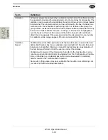
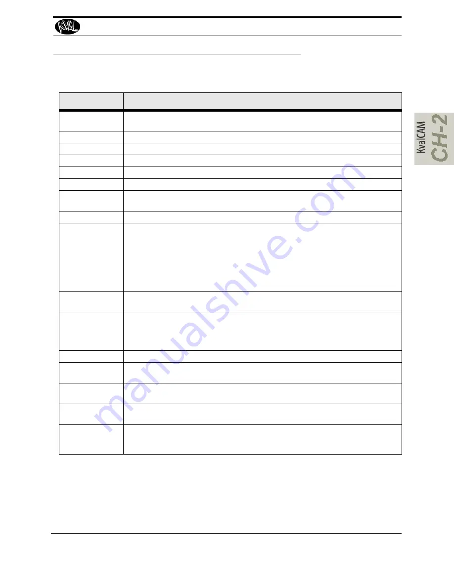
Definitions
Term
Definition
Library:
Working database for stored cuts (which are stored in the Template Library) and
doors/jobs (which are stored in the Door Job Library)
Job Name:
Name the Job that reflects the best description in your working environment.
Job Description:
Additional text field to describe the job when similar names are being used.
Created:
Date in which the feature or saved door/job was created.
Last Modified:
Date in which the feature or saved door/job was last modified.
Face Material:
Material that will be run on either Face of the door.
Hinge Material:
Material that will be run on the Hinge Side of the door. Wood/FG is the only valid
material type to run on the Hinge Side for this line.
Lock Material:
Material that will be run on the Lock Side of the door.
Feature Group
Also known as “Group” or “Template”, a Feature Group is a container in which indi-
vidual or multiple features can be loaded and cut into a door. Feature Groups oper-
ate at the root level of the feature tree, from which child features branch out.
All Feature Groups have their own L, T, and W location that is separate from the
features contained inside. This allows the user to quickly move templates to new
locations or to duplicate templates in multiple locations (by adding new locations to
the group).
Feature Group
Name:
This field is required when saving a new template.
Feature
Features are created by adding children to a feature group. All features are specific
cuts that can be made on a door. Feature Types for this line include Rectangle, Cir-
cle, Hinge, Tee-Shape, and G-Code, each with their own parameters and valida-
tion requirements.
Door Side:
Selection for which side of the door that a feature will be run on.
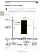
L Axis:
Located on the Door Preview Screen, the L (length axis) is represented visually
with changes of door reference.
W Axis
Located on the Door Preview Screen, the W (width axis) is represented visually
with changes of door reference.
T Axis
Located on the Door Preview Screen, the T (thickness axis) is represented visually
with changes of door reference.
Expression:
Inputted values by the user for an intended feature. The input is interpreted by the
program and passed through a validation scheme for all machines in a line to
determine if the intended cut is capable of being run (see validation).
Summary of Contents for EFX
Page 10: ...KVAL EFX Manual Table of Contents ...
Page 32: ...Safety Sign Off Sheet KVAL Operation Manual 1 22 ...
Page 66: ...About the LiteCutout Feature Detail DL NCD Only KVAL Operation Manual 2 34 ...
Page 95: ...Appendix About Backing up the Data 3 29 KVAL Operation Manual ...
Page 112: ...Step 4 Calibrate the Face Axes KVAL Operation Manual 4 17 X Y Z X Y Z Y ...
Page 121: ...Routers How to Isolate and Calibrate a Specific Router KVAL Operation Manual 4 26 ...
Page 136: ......
Page 138: ...Index 1 2 Kval EFX ...
Page 139: ......

