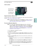
Step 6: Calibrate the Edge Carriage
KVAL Operation Manual
4-20
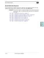
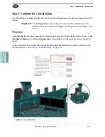
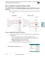
Step 6: Calibrate the Edge Carriage
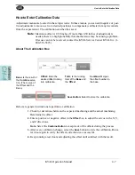
Process to Calibrate the Edge Carriage
In this calibration process, cut a known door lock on the edge of the door. Measure the location of
the cut.
1.
Before calibrating the tools, update the Tool Configuration of the tool being calibrated.
See “About Using Tool Configuration” on page 3-23.
2.
Create a
Lock Job
of your choice with a corner radius of 0.25 inches and a depth of
0.25 inches.
3.
Add
Door Job
to the
Queue
.
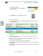
4.
Once the cut has been made, check the location of the cut.
5.
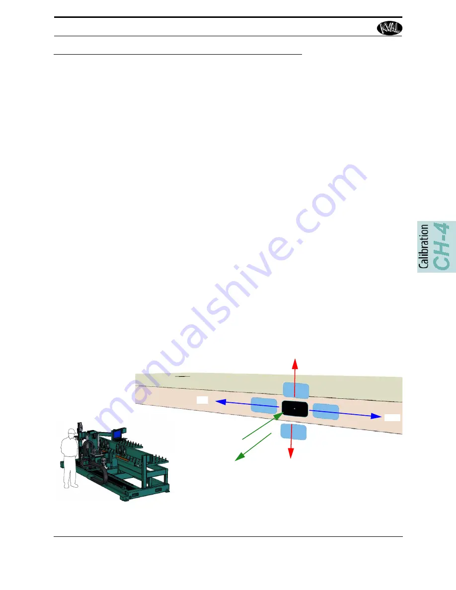
Perform the Left Hand Rule at the lock side of the door to determine axis direction. See
illustration below.
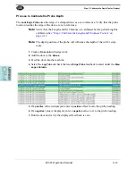
• If the location is out of specification in the
length
of the door edge, the
X-Axis
needs to be adjusted.
• If the location is out of specification in the
width
of the door edge4, the
Y-Axis
needs to be adjusted.
• If the plunge cut is out of specification, check the
Configuration Menu
then verify
the
Z-Axis.
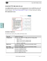
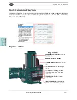
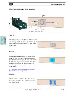
Edge Axis Calibration Reference Cut
The figure below, shows a sample reference cut and the type of offset to input into the calibration
menu.
See “How to Enter Calibration Data” on page 4-7
+
X
+
Y
+
Z
-
X
-
Z
-
Y
Summary of Contents for EFX
Page 10: ...KVAL EFX Manual Table of Contents ...
Page 32: ...Safety Sign Off Sheet KVAL Operation Manual 1 22 ...
Page 66: ...About the LiteCutout Feature Detail DL NCD Only KVAL Operation Manual 2 34 ...
Page 95: ...Appendix About Backing up the Data 3 29 KVAL Operation Manual ...
Page 112: ...Step 4 Calibrate the Face Axes KVAL Operation Manual 4 17 X Y Z X Y Z Y ...
Page 121: ...Routers How to Isolate and Calibrate a Specific Router KVAL Operation Manual 4 26 ...
Page 136: ......
Page 138: ...Index 1 2 Kval EFX ...
Page 139: ......


