Kvaser Eagle User's Guide
22(30)
Kvaser AB, Mölndal, Sweden
— www.kvaser.com
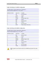
Table 8: CAN Channel 1 D-SUB Pin Configuration
The CAN channel 1 has the following pin configuration:
(Auto-reset fuses protect Pins 2, 3, 4, 7 and 9)
D-SUB pin number
Color code
Function
1
N/A
Not connected
2
Green
CAN_L
3
Brown
GND
4
Orange
External trigger input
5
Black
Shield
6
N/A
Not connected
7
Red
CAN_H
8
N/A
Not connected
9
Yellow
Power supply to the device
Table 9: CAN Channel 2 D-SUB Pin Configuration
The CAN channel 2 has the following pin configuration.
(Auto-reset fuses protect Pins 2, 3, 4, 7 and 9.)
D-SUB pin number
Color code
Function
1
N/A
Not connected
2
Green
CAN_L
3
Brown
GND
4
Orange
External trigger output
5
Black
Shield
6
N/A
Not connected
7
Red
CAN_H
8
N/A
Not connected
9
Yellow
Not connected
Note:
Always connect the ground pin on the D-SUB to the ground of your CAN
bus.


