Kvaser Memorator 2xHS v2 User’s Guide
18 (26)
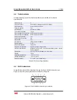
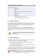
D-SUB pin number
Function
1
Not connected
2
CAN_L
3
GND
4
External trigger (CAN 1: Trigger input, CAN 2: Trigger output)
5
Shield
6
Not connected
7
CAN_H
8
Not connected
9
Power supply to the device (CAN 1 only)
Table 9: Configuration of the 9-pin D-SUB
4.4
CAN bus termination
Every CAN bus must be terminated with a 120 Ohm resistor at each end of the
bus. The Kvaser Memorator 2xHS v2 does not contain any CAN bus termination,
because their inclusion could cause severe disturbance in a system which is
already correctly terminated.
For laboratory or testing use, the exact value of the termination resistors is not
always critical. Sometimes a single terminator is sufficient. For production, proper
termination is essential. If you see error frames on the bus, you should check the
termination.
To save yourself a lot of trouble, always terminate the CAN
bus properly.
4.5
External trigger input
The Kvaser Memorator 2xHS v2 can be set up to trigger on an external signal and
can be configured to react on both falling and rising edges.
•
If it is set to trigger on a falling edge, the trigger is activated when the
External trigger is connected to ground.
•
If it is set to trigger on a rising edge, the trigger is activated when the External
trigger is disconnected from ground.
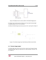
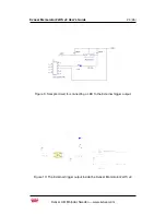
There are two ways to create such an external signal, either connect a switch from
the External trigger input on CAN channel 1 to ground or connect a signal between
0 and 5 V to the External trigger input. See Section 4.3, CAN connectors, on
Page 17 for pin numbering.
Kvaser AB, Mölndal, Sweden — www.kvaser.com


