22
54-0215 Rev. C
•
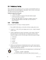
KVH recommends that you terminate the Tclk, Tdata, and Tsync lines as shown in
Figure 9. The values shown in this figure are simply starting values; you will need
to adjust them based on your particular application.
Figure 9: Recommended Line Terminations
4.3
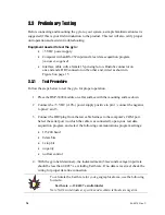
Preliminary Testing
Before connecting and mounting the gyro to your system, a simple familiarization test is
suggested if this is your first introduction to the product. This test will also verify proper
unit operation and assist in troubleshooting.
Equipment needed to test the gyro:
•
+5 VDC power supply
•
Interface cable with a female 15-pin single-row Dualobe connector,
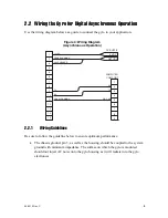
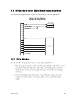
wired to your test application as shown in Figure 8 on page 21
4.3.1 Test
Procedure
Follow the steps below to test the gyro for proper operation.
1.
Place the DSP-3000 module on a flat surface with the mounting surface down.
2.
Connect the +5 VDC (±10%) power supply positive to pin 1; connect the negative
to pins 2 and 3.
3.
Connect the gyro to your test application. Be sure you terminate the “transmit”
lines as noted at the top of this page.
Tclk
100
Ω
100 pf
Tdata
100
Ω
100 pf
Tsync
100
Ω
100 pf

