54-0215 Rev. C
27
5.3
Preliminary Testing
Before connecting and mounting the gyro to your system, a simple familiarization test is
suggested if this is your first introduction to the product. This test will also verify proper
unit operation and assist in troubleshooting.
Equipment needed to test the gyro:
•
+5 VDC power supply
•
Voltmeter
5.3.1 Test
Procedure
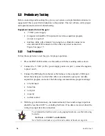
Follow the steps below to test the gyro for proper operation.
1.
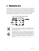
Place the DSP-3000 module on a flat surface with the mounting surface down.
2.
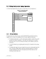
Connect the +5 VDC (±10%) power supply positive to pin 1; connect the negative
to pin 2.
3.
Connect the voltmeter across pins 4 (positive) and 5 (negative) of the gyro
interface connector.
4.
Grasp the gyro and slowly rotate it in the direction of the arrow on its serial
number label. The voltage (shown on the voltmeter) should increase.
5.
Slowly rotate the gyro in the opposite direction. The voltage (shown on the
voltmeter) should go negative.
6.
Connect the voltmeter across pins 8 (positive) and 6 (negative) of the gyro
interface connector. After the initial 5-second startup, the voltage should show
TTL Low (less than +0.6 VDC) at all times. If the BIT shows TTL High (greater
than +2.4 VDC), the gyro has malfunctioned.

