1
TracVision 6 Installation and Technical Manual – ADDENDUM
54-0166 Addendum to Rev. B
TracVision 6 Technical
Manual Addendum
(ECO #5503)
The following changes have been made to Revision B of the
TracVision 6 Installation and Technical Manual (KVH Part
Number 54-0166).
4.4
PCB Removal and Replacement
The CPU Printed Circuit Board (PCB) has been changed from an
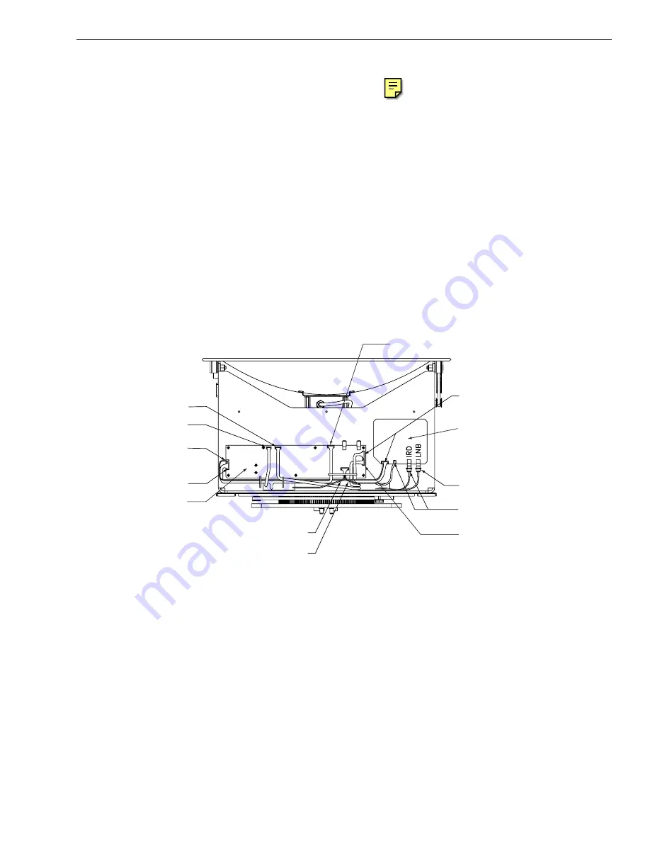
“L”-shaped design to a simpler straight design. Figure 4-3 has been
updated to show the new CPU PCB.
4.4.1 CPU Board
The new CPU Board is secured to the antenna frame using nine screws
rather than eleven.
2. Remove
nine
#6-32 machine screws from the PCB.
From Cable Wrap
From Azimuth Limit Switch
RFU PCB
From LNB
From Cable Wrap
RFU to CPU
From Antenna Sensor
From Elevation Limit Switch
CPU PCB
From Cable Wrap
From RFU to CPU Cable
From Azimuth Motor
From Elevation Motor
Figure 4-3
PCB Connector Locations
(Rear View)


