2
54-0166 Addendum to Rev. B
FRU
Part Number
European LNB Assembly
02-1278
U.S.-style LNB Assembly
02-0870
Latin American LNB Assembly
02-0870-01
Data Cable
32-0619-100
Switchplate
02-1023
RF Cable
32-0566-0100
PC Cable
32-0628-06
CPU Fuses
16-0017-3150
4.4
PCB Removal and Replacement
The printed circuit boards (PCBs) are protected by a cover
fastened to the antenna support frame. The cover must be
removed to gain access to the main power
fuses
and the
PCB assemblies discussed below. Refer to Figure 4-2; remove
3 nuts and washers from the bottom flange and 3 screws and
washers from the upper flange. Remove the cover and set aside
with the fasteners.
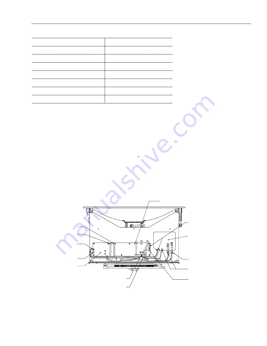
The CPU PCB has been changed from an “L”-shaped design to a
simpler straight design. Figure 4-3 has been updated to show the new
CPU PCB.
From Cable Wrap
From Azimuth Limit Switch
RFU PCB
From LNB
From Cable Wrap
RFU to CPU
From Antenna Sensor
From Elevation Limit Switch
CPU PCB
From Cable Wrap
From RFU to CPU Cable
From Azimuth Motor
From Elevation Motor
Figure 4-3
PCB Connector Locations
(Rear View)


