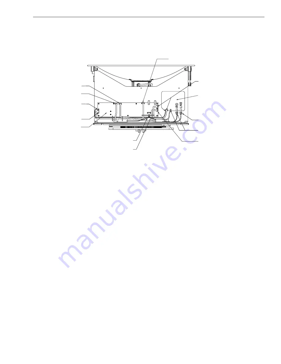
4.4.1 CPU Board
The new CPU Board is secured to the antenna frame using nine screws
rather than eleven.
2. Remove nine #6-32 machine screws from the PCB.
The following procedure has been inserted for replacing the azimuth
limit switch. As a result, Sections 4.6 through 4.8 of the Installation
and Technical Manual have been renumbered Sections 4.7 through 4.9.
4.6
Azimuth Limit Switch Assembly
Replacement
1. Rotate the antenna assembly, by hand, clockwise
until it stops.
2. Remove the printed circuit board (PCB) cover,
illustrated in Figure 4-2, using a #2 Phillips
screwdriver and a
3
⁄
8
" nut driver/socket.
3. At the CPU’s Molex connector, cut the black and
white wires from the azimuth limit switch (see
Figure 4-3). Leave about one inch (25 mm) of the
wires still connected for later reference.
3
TracVision 6 Installation and Technical Manual – ADDENDUM
54-0166 Addendum to Rev. B
From Cable Wrap
From Azimuth Limit Switch
RFU PCB
From LNB
From Cable Wrap
RFU to CPU
From Antenna Sensor
From Elevation Limit Switch
CPU PCB
From Cable Wrap
From RFU to CPU Cable
From Azimuth Motor
From Elevation Motor
Figure 4-3
PCB Connector Locations
(Rear View)


