31
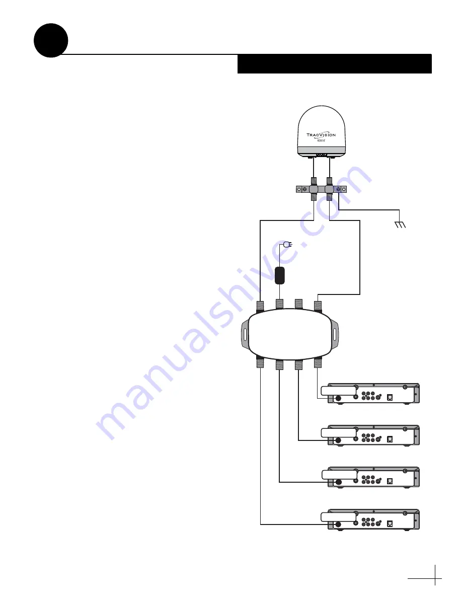
To connect three or more receivers to a circular
system, follow these steps to install an Eagle
Aspen multiswitch (KVH part #72-0310) between
the grounding block and the receivers, as shown
in Figure 51.
1. Connect an RF cable from the “RF1”
connector on the grounding block to the
“13V” connector on the multiswitch.
2. Connect an RF cable from the “RF2”
connector on the grounding block to the
“18V” connector on the multiswitch.
3. Connect the receivers to the individual
outputs of the multiswitch.
4. Connect the receivers to the customer’s TVs.
The use of a multiswitch interrupts satellite
switching communications between the receiver
and antenna. As a result, to switch between two
or three selected satellites, use the buttons on the
ADCU’s front panel (see the User’s Guide for
details).
S
ATELLITE IN
OUT TO TV
TV ANT/CABLE IN
AUDIO
VIDEO
S
-VIDEO
PHONE JACK
R
L
Satellite In
S
ATELLITE IN
OUT TO TV
TV ANT/CABLE IN
AUDIO
VIDEO
S
-VIDEO
PHONE JACK
R
L
Satellite In
S
ATELLITE IN
OUT TO TV
TV ANT/CABLE IN
AUDIO
VIDEO
S
-VIDEO
PHONE JACK
R
L
Satellite In
S
ATELLITE IN
OUT TO TV
TV ANT/CABLE IN
AUDIO
VIDEO
S
-VIDEO
PHONE JACK
R
L
Receiver #3
Receiver #2
Receiver #1
Receiver #4
Satellite In
RF2
RF1
Grounding
Block
Vessel
AC Ground
Ground Wire
RF2
RF1
AC Power Input
100-240 VAC
50-60 Hz
Multiswitch
Note: Although the label
shows “20V,” the unit
accepts a 24 VDC input.
13V
SAT
Rx4
ANT
IN
Rx3
DC
20V
Rx2
Rx1
18V
SAT
24 VDC
Power Supply
Figure 51: Multiswitch Wiring - Antenna with Circular Dual LNB
Wiring 3+ Receivers
A
Circular Systems


