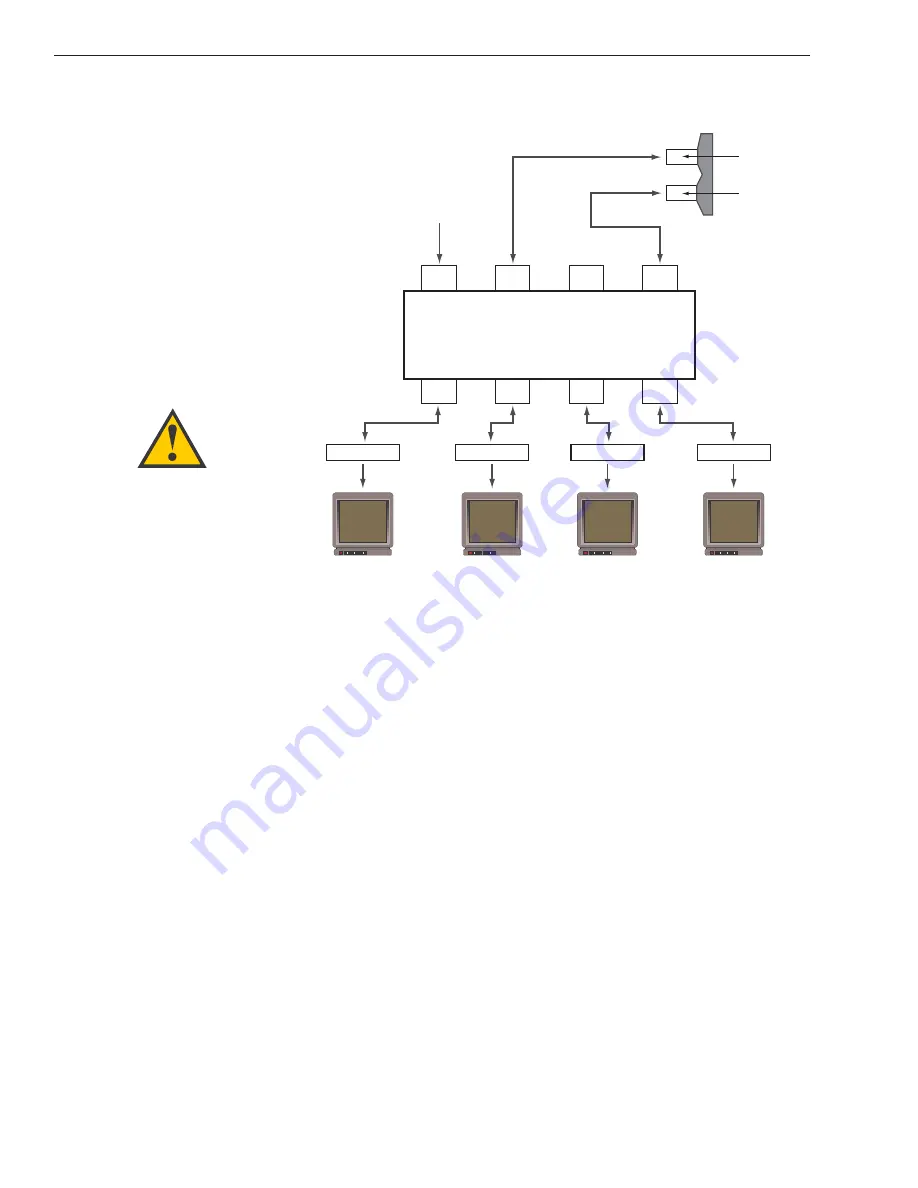
1. Connect the RF cable tagged “RF1” to the
multiswitch input labeled “LNB RHCP +13V”.
2. Connect a second RF cable to the multiswitch
input labeled “LNB LHCP +18V”.
3. Connect the multiswitch outputs to individual IRD
inputs. Use RG-6 cable terminated with
F-type connectors for all RF connections.
4. Terminate all unused output connectors with
75 ohm DC blocks (Channel Master #7184, Radio
Shack #15-1259 or equivalent).
Commissioning the IRD
Please refer to the user manual that accompanied your IRD for
instructions on properly commissioning the system.
2-16
A Guide to TracVision S3
Multiswitch
DC In
RHCP
+13v
VHF/UHF
LHCP
+18v
Out 1
Out 2
Out 3
Out 4
DC Power
IRD #1
IRD #2
IRD #4
IRD #3
TracVision S3 RF Connectors
RF1
RF2
Figure 2-25
Installing Three or More IRDs
Using an Active Multiswitch
(North American Systems Only)
TracVision S3 has the capability to
switch from one satellite to another
when you choose TV channels that
are carried by your two selected
satellites. However, the use of an
active multiswitch may interfere with
the 22 KHz tone sent by
IRDs to the antenna. As
a result, the antenna may not
receive the signal to change
satellites when you change
channels using your
remote.
In this case, you will need to use
the manual satellite switch
procedure explained in


