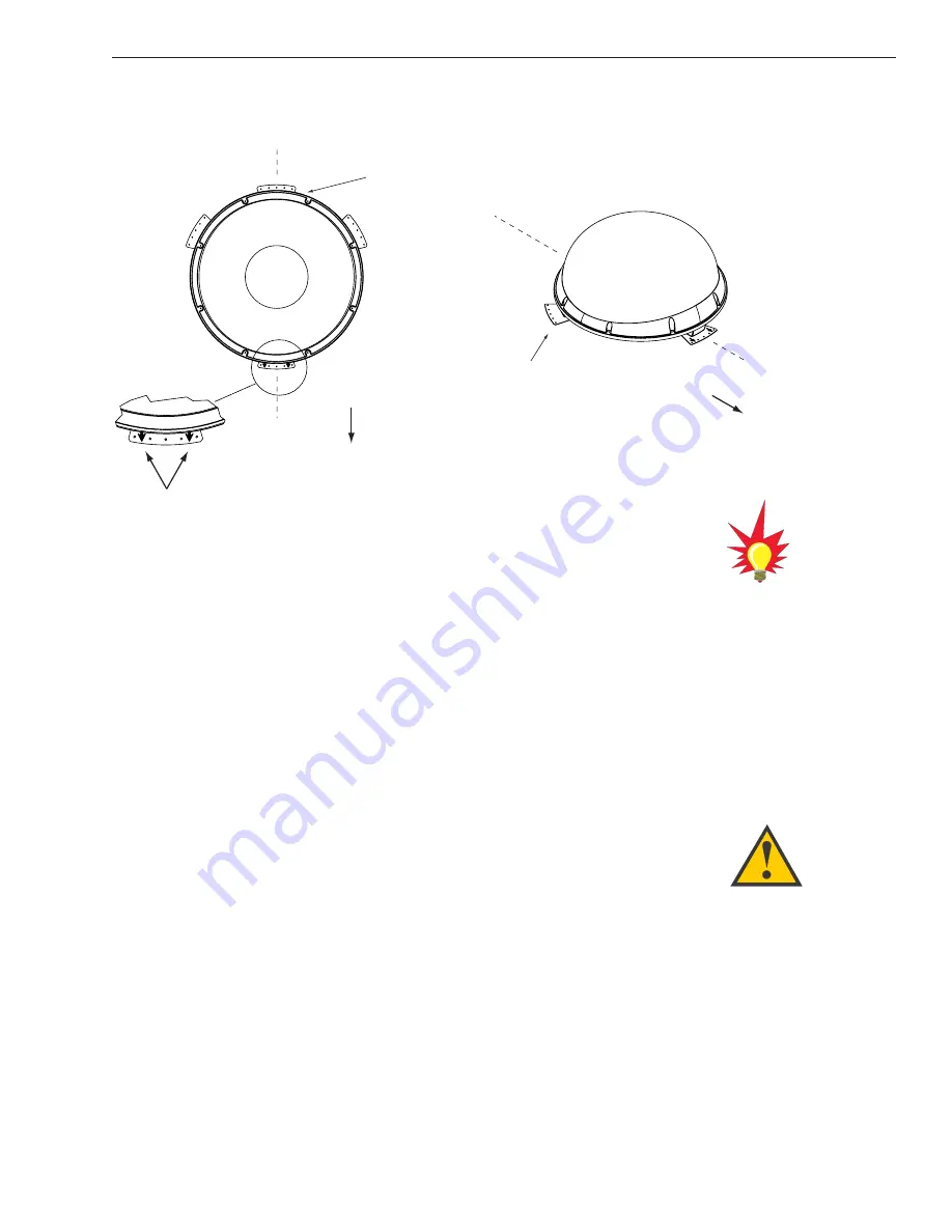
4. While the antenna is in place, mark a location on
the roof for the cable access hole to permit
convenient cable access to the antenna’s baseplate
connectors.
5. Using the 4 mounting plates and each set of 5
holes as templates, drill 20
3
⁄
16
"
(5 mm) holes
through the roof of the vehicle.
6. Set aside the antenna unit and clean the roof’s
surface to remove any debris.
7. Apply construction adhesive to the bottom of the
antenna’s four mounting plates. If using a liquid
construction adhesive, apply beads to the
mounting plates in a zig-zag pattern.
8. Reposition the antenna, lining up the mounting
plate holes with the holes in the roof. Attach the
mounting plates to the roof using
3
⁄
16
" (5 mm)-
diameter rivets (or appropriate fasteners). Seal all
rivet heads and edges with silicone.
9. Remove and save the 8 pan head screws and flat
washers that secure the radome to the baseplate.
Carefully lift the radome straight up until clear of
the antenna assembly and set aside.
3
A Guide to TracVision S3 – ADDENDUM
54-0182 Addendum to Rev. A1
Vehicle
Centerline
Vehicle
Center
line
Front/Rear
of Vehicle
Front/Rear
of V
ehicle
Top View
Side View
Mounting Plate
(1 of 4)
Baseplate
Connectors
Mounting Plate
Arrows
Figure 2-3
Proper Orientation of
the Antenna Unit
The mounting plate arrows may
face either forward or backward
along the centerline of the vehicle
for more convenient installation.
If the roof’s mounting surface is not
perfectly flat as KVH recommends,
make sure the baseplate does not
warp when you attach the
antenna’s mounting plates. Refer to
Section 2.1, “Choosing the Best
Location,” for further details.


