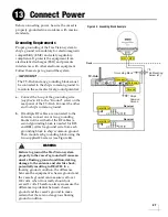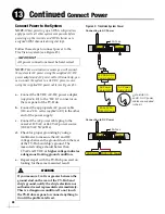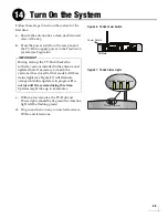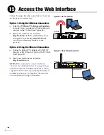
19
Connecting 5 or More Linear Receivers
a.
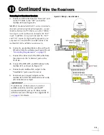
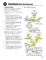
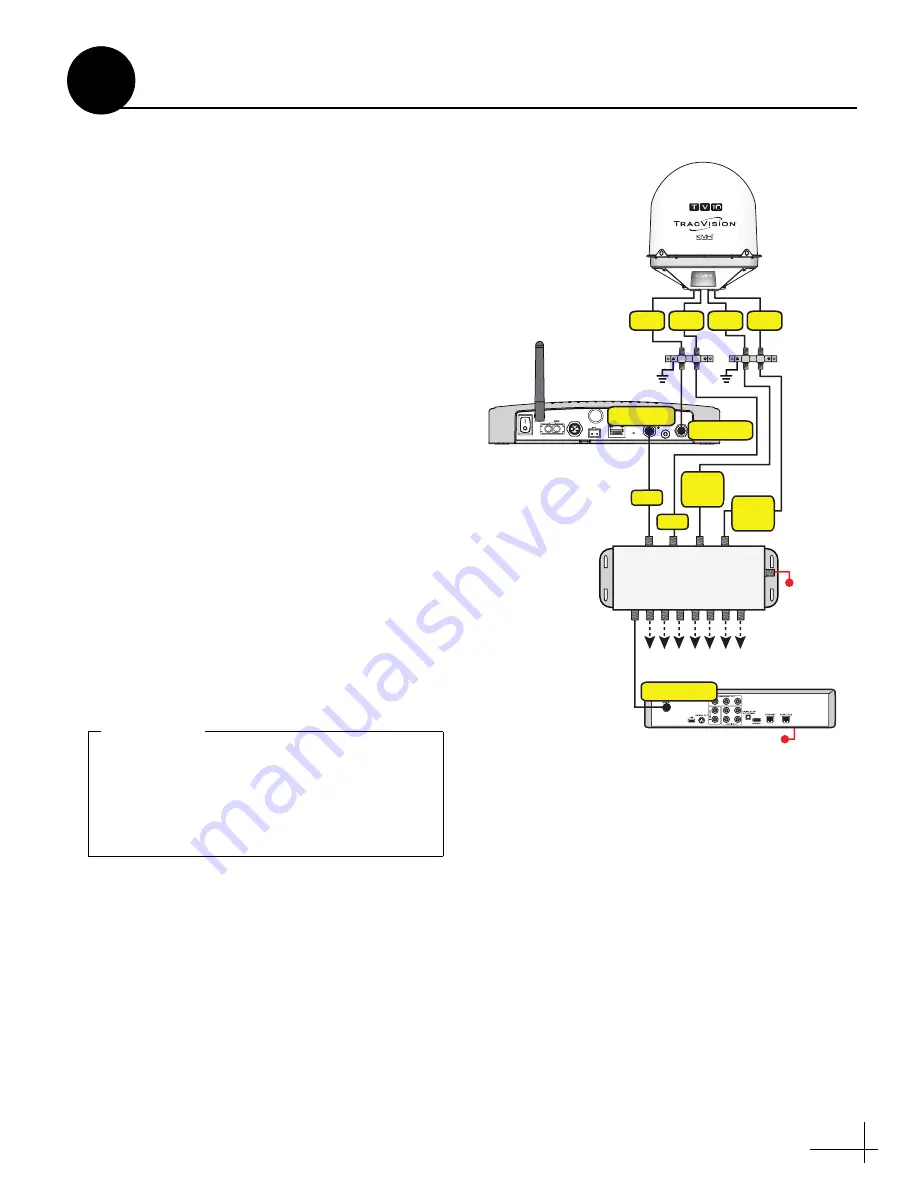
Connect an RF cable from the “Receiver” jack
on the TV-Hub to the “18V” jack on the
NOTE:
If the desired satellite TV service is limited to
channels carried on high-band transponders, connect
the RF cable from the TV-Hub to one of the “22KHz”
tone inputs on the multiswitch, instead of the “18V”
input. In addition, since you do not need the “18V”
and “13V” inputs for high-band transponders, you
only need to connect the RF1 and RF2 cables to the
multiswitch; RF3 and RF4 are unnecessary.
b.
Connect a grounding block in-line with each
RF cable from the antenna (see Figure 29 and
“Grounding Requirements” on page 27
c.
Connect the other end of the RF1 cable from
the antenna to the “Antenna” jack on the
TV-Hub.
d.
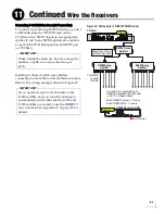
Connect the RF2, RF3, and RF4 cables to the
multiswitch, as shown in Figure 29.
e.
Connect each multiswitch output to the
“Satellite In” jack on each receiver.
f.
Terminate any unused outputs on the
multiswitch with 75
terminators and verify
all connections are tight.
Figure 29: Wiring 5+ Linear Receivers
TV-Hub
Wi-Fi
LEN=1
10-30V
POWER
MAX CURRENT 9.5A
NMEA 0183
B
A
FUSE
ETHERNET
DSWM
RECEIVER
GROUND
ANTENNA
RESET
NMEA 2000
DC IN
Antenna
Receiver
RF1
RF4
RF3
RF2
Receiver
AC Power
Satellite In
Connect up to 8 receivers
18V
13V
13V/
22
KHz
18V/
22
KHz
AC Power
13V
18V/
22KHz
13V/
22KHz
18V
Multiswitch
Grounding
Blocks
To enable any of the receivers to control
satellite selection, install an optional IP
AutoSwitch (KVH part no. 72-0634) in-line
with the receiver’s RF input. See Appendix B
on
for details.
IMPORTANT!
Continued
Wire the Receivers
11
Summary of Contents for TracVision TV10
Page 1: ...TracVision TV10 Installation Guide ...
Page 53: ......

