background image

kvm-tec    |    83

www.kvm-tec.com

Summary of Contents for 6701i

Page 1: ...LOCAL 6811R CON REMOTE Check out our Installation Channel Industryline MVX i 6701i SET 6701iL CPU LOCAL 6701iR CON REMOTE Industryline fiber MVXi F 6801 SET 6801iL CPU LOCAL 6801iR CON REMOTE USER MANUAL Industryline smart connections ...

Page 2: ...2 Installation of the extender 13 2 1 Unpacking and checking the contents 13 2 2 Mounting options 14 2 2 1 Mounting pads and rubber feet 14 2 2 2 Mounting kits optional 14 2 3 Installing the extender 15 2 4 Startup 20 2 5 Replacing the SFP module 20 2 6 Removing a CATx cable 21 2 7 Removing a fiber cable 21 3 1 How to access the main menu 22 3 2 Status Menu 23 TABLE OF CONTENTS ...

Page 3: ...pgrade 33 3 7 How to define what DDC information by the PC 34 3 8 How to change the network settings 34 3 9 How to change the extender settings 35 3 9 1 How to optimize VGA preferences 37 3 9 2 How to enable or disable the USB compatibility mode 38 3 9 3 How to set the baud rate for the RS232 39 3 9 4 How to show the last received image 41 3 9 5 How to turn on or off monitor synchronization 42 3 9...

Page 4: ...nected devices 53 4 3 How to manage user details rights and groups 55 4 4 How to view the status of all remote units 58 4 5 How to view the status of all local units 60 4 6 How to set up dual head or multi head systems 62 4 7 How to enable user groups and rights and login access 64 4 8 How to auto connect to a free computer after an interruption 65 4 9 How to set up a private connection 66 4 10 Ho...

Page 5: ...ranty 74 9 Support 74 10 Declaration of Conformity 75 11 1 Requirements for CAT5e 6 7 cables 77 11 Requirements for cables 77 11 3 Requirements network switch 78 11 2 Requirements fibER cables 78 11 2 1 Multi Mode standard 78 11 2 2 Single Mode optional 78 12 Requirements Network Switch 78 13 First Aid 80 14 Extended warranty 81 15 Notes 82 TABLE OF CONTENTS ...

Page 6: ...wing proper use and maintenance your Industryline MVXi MVXi F KVM Extender will bring you joy for many years to come 1 1 INTENDED USE This product is intended to be used as a device to increase the distance that a keyboard monitor and mouse can be placed from a computer This product is intended for professional use The product should not be used in potentially explosive environments The product ma...

Page 7: ...ilant at all times and always take care around this product Do not use electrical equipment if you are lacking in concentration or awareness or are under the influence of drugs alcohol or medication Even a moment of inattentiveness can lead to serious accidents and injuries when using electrical equipment Check the product and the cables for any damage before use If there is any visible damage a s...

Page 8: ... the adapter with wet hands Use the product within the specified performance limits Keep the product away from flammable materials such as curtains and drapes Protect the mains adapter from use by third parties particularly children Keep the unused mains adapter in a dry elevated or locked location away from children Do not place the product near heaters Do not drop or hit the product Unplug all c...

Page 9: ...ng attached USB devices Operating temperature range 0 ºC to 45 ºC 32 F to 113 F Storage temperature range 25 ºC to 80 ºC 13 F to 176 F Relative humidity max 80 non condensing Storage humidity max 80 non condensing Casing Material Anodized aluminium Dimensions approx 97 5 x 41 x 103 5 mm 3 83x 1 57 x 4 7 inch Weight local unit 302g 0 66lbs remote 291g 0 64lbs Expected product life 82 820 hours 9 5 ...

Page 10: ...Function 1 dvi in DVI connection to PC 2 DC in Connection power supply 12 24V 3 kvm link RJ45 socket Connection for CAT5 6 7 cable or fibre cable 4 usb USB connection 5 gnd ground screw 6 dvi out DVI connection to monitor 7 Power Status LED Display the status of the Extender ...

Page 11: ...n 8 DC in connection power 12 24V 9 USB USb connectionfor keyboard and mouse 10 gnd ground screw 11 kvm link RJ45 socket Connection for CAT5 6 7 cable or fibre cable 12 dvi out DVI D connection to monitor 13 Power Status LED Displays the status of the extender 1 ...

Page 12: ...y Table 1 Meaning of LED indicators Colour Blinking Physical Link Active Connection Video Extended USB Initialisation UBS Data Received Identify Command Autoupdate Mode Red Yes No No Update Failed Red Slow No No No Orange Yes Yes No Orange Fast Update in Progress Green Yes Yes Yes Update Succedded Green V fast Yes Red Green V fast Yes Yellow No Yellow Slow Yes Green Yes Green V fast Yes Main LED R...

Page 13: ...afety Make sure that the packaging contains the following content A 1x MVXi local extender CPU without power supply B 1x MVXi remote extender CON without power supply LOCAL UNIT CPU 1 x Power Connector 1 x DVI DVI cable 1 8m 5 9ft 1 x USB cable 1 8m 5 9ft 1 x VGA DVI cable 1 8m 5 9ft opt 4 x rubber feet 4 x mounting pads REMOTE UNIT CON 1 x Power Connector 4 x rubber feet 4 x mounting pads INDUSTR...

Page 14: ...nsists of a19 rack shelf and an alu faceplate Rack Mounting Kit RMK FN Part No 6131 The rack mounting kit RMK FN is for assembling kvm tec Industryline MVXi Extender It consists of 19 Rack Shelf an alu faceplate and a power supply Rack Mounting Kit RMK FRN Part No 6132 The rack mounting kit RMK FRN is used to mount kvm tec Industryline MVXi Extender It is equipped with rack shelf faceplate and 2 p...

Page 15: ... can be set up to access one host computer or to access numerous host computers In the case of the latter an additional Network Switch must be installed With a Network Switch each user can gain quick access to any of the required computers point to point connection Set up for Switching System up to 48 endpoint Set up for Switching Systgem up to 48 endpoints 2 ...

Page 16: ...ENDER 1 power plug 12 24 VDC 4 DVI in from PC 2 USB to PC 4 DVI out from Monitor 1 power plug 12 24 VDC 2 USB from Kayboard and Mouse 3 Network cable CAT 5e 6 7 up to 150m 492ft 4 D V I t o M o n i t o r earth connection earth connection ...

Page 17: ...the other end of the USB cable to the CPU Local Unit Connect keyboard and mouse to the CON Remote Unit 3 Connect the CPU Local and the CON Remote Unit with a network cable 4 Now connect the HDMI DVI cable to the DVI socket of the PC and the other end to the HDMI socket of the CPU Local Unit PC in Then connect the monitor with the HDMI DVI cable to the CON Remote Unit HAVE FUN your kvm tec Extender...

Page 18: ...DER 1 power plug 12 24 VDC 4 DVI in from PC 2 USB to PC 4 DVI out from Monitor 1 power plug 12 24 VDC 2 USB from Kayboard and Mouse 3 Duplex Multimode Fiber cable up to 500m 1640ft 4 D V I t o M o n i t o r earth connection earth connection ...

Page 19: ...the other end of the USB cable to the CPU Local Unit Connect keyboard and mouse to the CON Remote Unit 3 Connect the CPU Local and the CON Remote Unit with a network cable 4 Now connect the HDMI DVI cable to the DVI socket of the PC and the other end to the HDMI socket of the CPU Local Unit PC in Then connect the moni tor with the HDMI DVI cable to the CON Remote Unit HAVE FUN your kvm tec Extende...

Page 20: ... red status LED blinks a few seconds After a few seconds the status LED lights green The monitor will displays your computer s desktop or any open applications 2 5 REPLACING THE SFP MODULE The MVX1 F is delivered with a multimode SFP module To replace an SFP module with a different SFP module 1 Remove the black dust protector from the SFP module 2 Pull the metal latch of the SFP module forwards un...

Page 21: ...ION OF THE EXTENDER 2 2 6 REMOVING A CATX CABLE To remove a CATx cable Press the latch down and slowly pull the cable out 2 7 REMOVING A FIBER CABLE To remove a fiber cable Press the latch down and slowly pull the cable out ...

Page 22: ...ars with an overview of the sub menus 3 To access a sub menu press the applicable key In the main menu you can make the following settings by pressing the to select the corresponding letter T Status Overview Menu Status Current Status U Update Flash FW Update firmware M Option Overview Overview of all upgrades O DDC Option DDC Option Fixed ice position 1020 x 1080 W Network Settings Network Settin...

Page 23: ...n the connection itself as well as resolution of the video channel and USB status The enabled options and the current FW version is displayed in the left top corner Link status shows whether there is a physical connection available Connection indicates if kvm data is currently able to be transmitted Video and USB show if data is currently being transmitted ...

Page 24: ... MENU SETTINGS 3 3 HOW DETERMINE THE CURRENT FIRMWARE VERSION To view the firmware version Make sure the main menu is open The currently installed firmware versions of the remote and local units are displayed below e g 4267 ...

Page 25: ...he update process There are four ways to perform an update 1 update via a bitmap image 2 update from the USB stick 3 automatic update 4 network update To perform a firmware update 1 Make sure the main menu is open 2 Press the U key The Update menu appears Press the N key to do a network update Press the A key to do an automatic update Press the U key to do a direct update Press the S key to do a U...

Page 26: ...ITMAP IMAGE The file will be output from an image and will be copied and storede to the currently connected extenders Wait until all 3 phases of the update have been completed and make sure that you have Never unplug or plug in the devices during the update ...

Page 27: ...ick the following steps are necessary 1 you receive the message that you can plug in the USB stick 2 copy the update file ending in kvm to the USB stick 3 make sure that the update file is directly on the stick and that it is not in any subdirectory 4 the USB stick must be formatted with FAT 32 ...

Page 28: ...28 kvm tec 3 EXTENDER MENU SETTINGS Plug in the USB stick and wait for a moment ...

Page 29: ...kvm tec 29 3 EXTENDER MENU SETTINGS Wait until all 4 phases have been completed ...

Page 30: ...AUTOUPDATE You can select in the menu which part should be updated As soon as the devices are connected the firmware is copied from one unit to the other The flashing of the LEDs indicates that the update process has been completed the LEDs are then green ...

Page 31: ...network update the devices that are updated can be marked The information is then sent to the marked units During this process the devices can still be in operation As soon as all updates have been transmitted the marked devices can be restarted and start with the new firmware ...

Page 32: ...ial number of the KVM Extender 4 4 press the M key to enter the unlock code 5 enter the unlock code of the supplier 6 the Extender will automatically restart To confirm that the option has been unlocked return to the Options menu Overview and make sure that the corresponding option is now green The information is then sent to the marked units During this process the devices can still be in operati...

Page 33: ... extender If your extender was provided with the USB Memory upgrade you can enable and disable at any time To enable or disable the USB Memory upgrade 1 Make sure the main menu is open 2 Press the M key The Options Overview menu opens The current USB Memory status is displayed Enabled or Disabled 3 Press 1 to enable or 0 to disable the USB Memory upgrade The kvm tec feature USB save prevents the i...

Page 34: ... main menu is open 2 Press the O key The DDC Option menu appears Press 0 to use the DDC information from the monitor attached to the remote extender Press 2 to save the current DDC information The system uses the same settings after the extender has been restarted Press 4 through 8 to use a predefined resolution which is saved 3 Press ESC to go back to the main menu 3 8 HOW TO CHANGE THE NETWORK S...

Page 35: ...Three of the selections VGA Audio and RS232 will take you to sub menus The other four can be enabled or disabled by pressing the applicable key To access the Extender Settings menu 1 Make sure the main menu is open 2 Press the G key The Extender Settings menu appears 3 The extender settings are distributed across two sub menus Remote Settings and Local Settings ...

Page 36: ...36 kvm tec 3 EXTENDER MENU SETTINGS 4 To access the local or remote extender settings Press the L key to access the Local Settings menu Press the R key to access the Remote Settings menu ...

Page 37: ...a down Press F2 to move the display area to the left Press F3 to move the display area to the right Press F5 to zoom out Press F6 to zoom in Press space to change the rate of the above mentioned setting This toggles the rate of change between 1 and 10 Press M to switch the video mode between Auto the mode is automatically detected and set by the extender DVI only DVI input is detected VGA only VGA...

Page 38: ...E USB COMPATIBILITY MODE The USB compatibility mode can be enables or disabled To enable disable the USB compatibility mode 1 From the Extender Settings menu press the L key The Local Settings menu appears 2 Press the U key to enable or disable the USB compatibility mode ...

Page 39: ...L CONNECTION To set the baud rate 1 From the Extender Settings menu press the R key The Remote Settings menu appears 2 Press the R key The Baud Rate menu appears 3 To select a baud rate press the applicable key The Enter Parity menu opens 4 To select a parity rate press the applicable key ...

Page 40: ...et in the menu There is a universal setting for baud rates up to 9600 which transmits all different RS232 configurations transparently For higher baud rates the following settings are available via the menu Baudrate Parity Stopbits 4800 No 1 9600 Odd 2 19200 Even 38400 Mark 57600 Space 115200 230400 T Remote Unit Pinout DTE Pin Function Direction 2 RxD IN 3 TxD OUT 4 DTR OUT 5 GND 8 CTS IN ...

Page 41: ... not being used by the local Extender CPU are separated To show that this is the last received picture the frame of the image flashes red Activate or deactivate the Show last Image function 1 1 In the Extender Settings menu press the R button The Remote Settings menu becomes Press S to activate or deactivate the function 2 press S to activate or deactivate the function 3 press ESC to return to the...

Page 42: ... match one another The advantage of this is to ensure that transmission remains smooth when the screen content changes rapidly e g When using multimedia applications Not all monitors support this method so by default this option is disabled To turn on monitor synchronization 1 From the Extender Settings menu press the R key The Remote Settings menu appears 2 Press the I key to enable or disable th...

Page 43: ...he extender menu can be locked When enabled the extender locks 5 minutes after start up to prevent unauthorized access To lock or unlock the menu 1 From the Extender Settings menu press the R key The Remote Settings menu appears 2 Press the L key The Menu Lock Menu appears ...

Page 44: ...out when the remote extender does not receive a video signal for more than a minute To turn on or off the power saving mode 1 From the Extender Settings menu press the R key The Remote Settings menu appears 2 Press the P key to enable or disable the power saving mode 3 When in power saving mode press any key to return to the menu ...

Page 45: ...ng the on screen display menu OSD You can choose between French Azerty English Qwerty and German Qwertz To select a keyboard layout 1 From the Extender Settings menu press the R key The Remote Settings menu appears 2 Press the K key The Keyboard Locale menu opens Press E to select English QWERTY Press D to select German QWERTZ Press F to select French AZERTY ...

Page 46: ...S 3 9 9 HOW TO CHANGE THE KEYBOARD FALLBACK MODE To change the keyboard fallback mode 1 From the Extender Settings menu press the R key The Remote Settings menu appears 2 Press the O key to change the keyboard fallback mode to 0 1 or 2 ...

Page 47: ...ettings menu press the R key The Remote Settings menu appears 2 Press the H key The Keyboard Shortcuts menu opens 3 Use the arrows to select a command 4 Press E to edit the shortcut To edit Press a single key Edit the frequency with left and right arrows OR Press a key combination 3 9 11 HOW TO CLOSE THE EXTENDER SETTINGS MENU To close the Extender Settings menu Press Q to close the Extender Setti...

Page 48: ...es that the Extender has been discon nected from the network If this is the case the computer can be removed from the switching menu with the delete key 2 Use the arrow up and arrow down keys or PGUP and PGDOWN keys to select a local extender Press enter The system switches to the selected computer The left column defines the favourites menu and provides each computer with a favourite number Each ...

Page 49: ...ER VIEW connections overview menu opens 3 Choose one of the following To mirror a screen to other consoles Press the P key on the keyboard of the extender that should display the user s screen In this case P stands for push to screen Such a command is only valid if the console which initiates the mirroring is currently connected to a local unit and has video and the other remote unit is free marke...

Page 50: ...50 kvm tec 3 EXTENDER MENU SETTINGS Videosharing ...

Page 51: ...itching Option Note this menu is only available when the Switching Option has been unlocked see chapter How to unlock an Option To access the Network Settings menu Master View and Network Mode 1 Make sure the main menu is open see chapter How to access the main menu 2 Press the W key The Enter User Password window opens kvm tec 51 4 NETWORK SETTINGS ...

Page 52: ... Master View option allows the administrator to view add edit or remove user console and computer information Press the V key to access the Master View menu The Network Mode allows to define how you want the network system to operate Each of the modes available may individually be activated or deactivated by pressing the appropriate key You may have more than one selected depending on their functi...

Page 53: ...iew of the current connections as well as the free PCs and consoles on the network You may break a connection remotely or assign a PC a new console or vice versa To force disconnect or select a workstation from the current connected devices 1 Make sure the Master View menu is open see chapter How to access the Network Settings menu Master View and Network Mode ...

Page 54: ...erview menu opens 3 Press the I key The Connection Details window opens Press the D key to force disconnect the selected device connection Press the E key or Enter key to select a PC or workstation to create or break a connection to that unit Press the Q key to exit ...

Page 55: ... GROUPS The Console Extender List allows you to manage user details rights and groups To manage user details rights and groups 1 Make sure the Master View menu is open see chapter How to access the Network Settings menu Master View and Network Mode 2 Press O to exit the menu ...

Page 56: ...ETWORK SETTINGS 2 Press the U key The User List menu opens Press the A key to add a new user Press the R key to delete the selected user Press the I key to display details about the selected user which may be edited ...

Page 57: ... user can be changed The rights control access to the Network Settings menu only ADMIN and which users may interrupt the connection of which other users Admin May interrupt connections of Masters and Users In the case that an Admin interrupts the connection of another Admin the interrupted Admin may reclaim the original connection Private connections can t be interrupted Master May interrupt conne...

Page 58: ...r PC Binding mode see 4 10 each user must have a PC bound to them That user will only be able to connect to that PC When selected the User Detail menu press RETURN a list of PCs on the network will be displayed to select from 4 4 HOW TO VIEW THE STATUS OF ALL REMOTE UNITS The Console Extender List allows you to view all remote units in the switching network and their current status To view the sta...

Page 59: ... this defines the extender which you are currently using in use indicates that the extender is in use free indicates that this extender is not busy 3 To edit the name of an extender press the I key The Console Extender Detail menu opens 4 Press the E key to edit the name of the extender ...

Page 60: ...t allows you to view all local units in the switching network and their current status To view the status of all local units 1 Make sure the Master View menu is open see chapter How to access the Network Settings menu Master View and Network Mode 2 Press the P key The PC Extender List menu opens ...

Page 61: ...lowing 3 PC s Department PC Team A PC and Team B PC The users Alex Blair and Charlie should have access to the Department PC and the Team A PC The users Danny Em and Frankie should have access to the Department PC and the Team B PC To achieve this we assign each PC a different group Department PC Group 1 Team A PC Group 2 Team B PC Group 3 Alex Blair and Charlie are assigned to be members of Group...

Page 62: ...group individual local and remote units together in the Multi Head menu making them switch as a single unit To group individual local and remote extenders 1 Make sure the Master View menu is open see chapter How to access the Network Settings menu Master View and Network Mode 2 Press the M key The Multi Head configuration menu opens ...

Page 63: ...ss the R key to remove an extender from the multi head set Press the Q key to exit 4 Press the A key to add individual extenders The extender type is automatically determined once the first extender has been selected 5 Press the E key to edit the multi head set name of max 16 characters ...

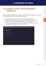
Page 64: ...ut user groups and rights see How to manage user details rights and groups Access to the network settings is always protected by a login and password even when the password system is disabled To enable the password option 1 Make sure the Network Mode menu is open see chapter How to access the Network Settings menu Master View and Network Mode 2 Press the P key to disable or enable the option ...

Page 65: ...automatically with a free computer if your connection is interrupted by another user This function is unavailable while using the Password System To enable the auto connect option 1 Make sure the Network Mode menu is open see chapter How to access the switching menu Master View and Network Mode 2 Press the C key to disable or enable the option ...

Page 66: ... the private connection option 1 Make sure the Network Mode menu is open see chapter How to access the switching menu Master View and Network Mode 2 Press the V key to disable or enable the option 3 To establish a private connection hold down Shift while you select a new connection either in the switching menu or by pressing the hot key combination see chapter How to switch between different compu...

Page 67: ...HOW TO ENABLE THE USER PC BINDING MODE To enable the User PC Binding mode 1 Make sure the Network Mode menu is open see chapter How to access the switching menu Master View and Network Mode 2 Press the B key to disable or enable the option ...

Page 68: ...tion of any local unit that is connected to a PC that is powered down allowing the remote unit to find a different local extender to connect to To enable the PC Power Down option 1 Make sure the Network Mode menu is open see chapter How to access the switching menu Master View and Network Mode 2 Press the D key to disable or enable the option ...

Page 69: ... 12 HOW TO HIDE INFO DISPLAY To hide the info display during startup 1 Make sure the Network Mode menu is open see chapter How to access the switching menu Master View and Network Mode 2 Press the H key to disable or enable the option ...

Page 70: ... ON STARTUP To reconnect on startup 1 Make sure the Network Mode menu is open see chapter How to access the switching menu Master View and Network Mode 2 Press the T key to disable or enable the option 4 14 VIDEO SHARING See chapter How to share videos ...

Page 71: ...r their login details when switching I Immediately User and password must be re entered for each switch N Never User and password are not required to be re entered until the current user logs out See chapter How to switch between different computers T Time in min You define the number of minutes since the last switch before the user and password details are required again to switch ...

Page 72: ...if the local PC cable is connected well Check if the remote monitor cable is connected well If everything is connected well but no function appears reconnect power supply again If the menu is visible press the O key and choose the resolution of the monitor Then press the assigned number on your keyboard LED is lighting green Screen occurs but the keyboard is not working Plug out in USB of keyboard...

Page 73: ... waste electrical and electronic equipment within the EU and in other European countries that operate separate collection systems for waste electrical and electronic equipment By disposing of the product in the proper manner you help to avoid possible hazards for the environment and public health that could otherwise be caused by improper treatment of waste equipment The recycling of materials con...

Page 74: ...RANTY If you have any questions about our products please contact your dealer kvm tec electronic gmbh Gewerbepark Mitterfeld 1A 2523 Tattendorf Austria Phone 0043 0 2253 81 912 Fax 0043 0 2253 81 912 99 Email support kvm tec com Web www kvm tec com Find our newest updates and FAQs on our homepage http www kvm tec com support 9 SUPPORT kvm tec Inc USA Sales p 1 213 631 3663 43 225381912 22 email of...

Page 75: ...e directive 2014 30 EU EMV directive The device was tested in a typical application with a PC RoHS II EU Directive 2011 65 EU Certificate according to RoHS II Directive 2011 65 EU We hereby certify that all our products are manufactured and packaged in accordance with RoHS II 2011 65 EU and PFOS 2006 122EG directives REACH Regulation EG No 1907 2006 For our products we only use commercially availa...

Page 76: ... EN 55032 2012 Class A EN 55024 2010 EN 61000 3 2 2014 EN 61000 3 3 2013 EN 60950 1 2006 A2 2013 IEC 60950 2005 LASER CLASS 1 EN 60825 1 2007 compatible with IEEE 803 3z Signed for and on behalf of KVM TEC Electronic GmbH Place and date of issue Tattendorf 2018 05 09 Name Function Signature Ing Dietmar Pfurtscheller CEO Geschäftsführer ...

Page 77: ...ust at the very least meet the CAT5 specifications and be suitable for Gigabit transmission The cable should meet one of the following standards Class D ISO IEC 11801 2002 or EN 50173 1 2002 Schema EIA TIA 568 B Only use shielded installation cable with min cross section of 24 AWG throughout the length The shield should be contiguous and connected to both ends A shielded patch cable is allowed for...

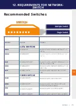
Page 78: ...connector A fiber Single Mode SFP Module BiDi cable should meet the following requirements Up to 20 km transmission distance Requires dedicated fibre connection cable type Singlemode with LC connector Wavelength λ of 850 nm in multi mode or 1310 nm TX 1550 nm RX in single mode 11 REQUIREMENTS FOR CABLES 12 REQUIREMENTS NETWORK SWITCH The entire switching network system requires its own dedicated n...

Page 79: ...J45 1000 Base T 2x SFP 1G 2x SFP 10G 6155 NS48RJ 4SFP Network Switch 48x RJ45 1000 Base T 4x SFP 10G 6171 NS48RJ 2SFP Network Switch 48x RJ45 10G 2x SFP 10G FIBER SWITCHE 6146 NS24SFP 4SFP Network Switch 24x SFP 4x SFP 6166 NS48SFP 4SFP Network Switch 48 x SFP 4x SFP with redundancy power supply 6151 NS32SFP 2QSFP Network Switch 32 x SFP 2x QSFP 6161 NS48SFP 4QSFP Network Switch 48x SFP 10G 4x QSF...

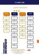
Page 80: ... is causing the problem by swaping first the local and than the remote Unit to ano ther Unit Contact kvm tec support Check if all cables are plugged in correctly Check if the PC is sending a Image by plugging in a monitor on the local out of the local Unit Check if the DDC is set correctly in menu under point O Check if both Units have the correct firmware No Video Contact kvm tec support Check if...

Page 81: ...kvm tec 81 14 EXTENDED WARRANTY 2 years warrnaty Part nr 9003 Warranty extension to 5 years per set Part nr 9002 Warranty extension to 5 years per uni ...

Page 82: ...82 kvm tec 12 15 NOTES ...

Page 83: ...kvm tec 83 www kvm tec com ...

Reviews: