


40 | kvm-tec
kvm-tec | 41
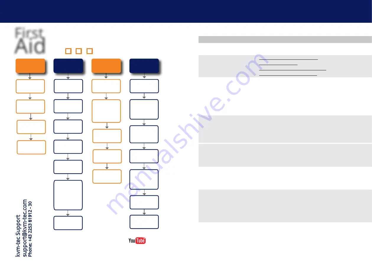
First
Aid
kvm-tec
smart connection
We are here for you to answer
your questions about installation?
Manual download www.kvm-tec.com
or
kvm-tec Installationchannel on our homepage
personally +43 2253 81912
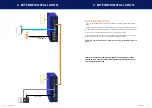
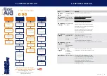
Video error
(stripes
in the picture)
USB is not working
No Power
(No LED)
Check the
powerplug
Is the power supply
ok? Try another Unit.
Try reprogramming the
Unit by using a JTAG
programmer
Contact kvm-tec
support
Are the USB
Devices plugged in
correctly?
Is the USB cable on the
Local side plugged into
the PC?
Are the USB
Devices working direc-
tly on the PC?
Check if local and
remote Unit have the
same firmware
Replace the USB cable
from PC to the Local
Extender
Check if the local or
the remote Unit is
causing the problem
by swaping first the
local and than the
remote Unit to ano-
ther Unit
Contact kvm-tec
support
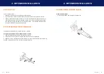
Check if all
cables are plugged in
correctly
Check if the PC is
sending a Image by
plugging in a
monitor on the local out
of the local Unit
Check if the DDC is set
correctly (in menu under
point „O“)
Check if both Units
have the correct
firmware
No Video
Contact kvm-tec
support
Check if all
cables are plugged in
correctly
Check if the PC is
sending a Image by
plugging in a monitor
on the local out of the
local Unit
Check if local and remote
Unit have the correct
firmware
Check if the DDC is set
correctly (in the menu
under point „o“)
Check if the network
switch is setup cor-
rectly and has enough
bandwidth
Contact kvm-tec
support
Check if other units have
the same
behaviour
kvm-tec Support support@kvm-tec.com
Phone: +43 2253 81912 - 30
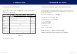
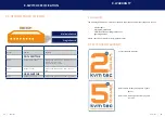
6. SUPPorT & fIrST aID
error
cause
solution
leD is not
lighting
The devices get no
power
Is the power supply connected?Ne start device
leD is lighting
in red
No connection
between Loc and
Rem
Check if the RJ45/network cable is connected well.
(Clicking noise when plugging in)
Control both, if it does not work please send an e-mail to
support@kvm-tec.com or phone +42 2253 81912
leD is lighting
in orange
No picture on the
monitor
Check if the local (PC) cable is connected well.
Check if the remote (monitor) cable is connected well.
If everything is connected well but no function appears,
reconnect power supply again.
If the menu is visible, press the O key and choose the
resolution of the monitor. Then press the assigned
number on your keyboard.
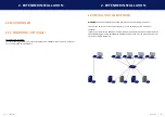
leD is lighting
in green
Screen occurs but
the keyboard is
not
working
Plug out/in USB of keyboard and wait until driver is
installed (after few seconds).
Check all USB connections on both sides (Local and
Remote)
If it is still not working, plug out/in USB once more
6. SUPPorT & fIrST aID
leD is lighting
in green
The screen
flikers,
has an incorrect
display
Install current fi rmware from our homepage http://www.kvm-tec.com/support
leD is lighting
in green
Different
firmware
or USB is not
compatible
Please contact the kvm-tec support team via e-mail:
support@kvm-tec.com or by phone: +43 2253 81912 30
LEDS different
different firmware
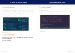
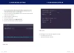
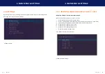
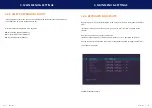
To enter on screen menu/check firmware version:
To enter the On screen menu, press the Scroll Lock key
five times in quick succession. The currently installed
firmware version is displayed below the menu
If firmware update does not work, please send an e-mail
to support@kvm-tec.com