Diajekt Control CFC10
10
Status: 06/18/2014
1.3.2 Electric Connections
External appliances and connections are connected to the control with bushing clamps. The
bushing clamps are numbered serially. The configuration of the bushing clamps is shown in table
3 below.
Table 3: Recommended configuration of PG fittings on the casing
PG fittings
Configuration
Connection
PG01
Power supply
Inlet
PG02
Connection chimney fan
Outlet
PG03
Connection draught regulator
(optional)
Outlet
PG04
Connection boiler release 1
In/Outlet
PG05
Connection boiler release 2
(optional)
In/Outlet
PG06
Connection alarm
(optional)
Outlet
PG07
Connection CF interface
(optional)
In/Outlet
PG08
Connection pressure sensor
Inlet
PG09
Connection thermal element
(optional)
Inlet
PG10
Connection extension module
(optional)
In/Outlet
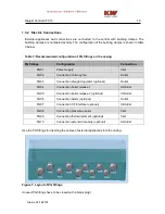
Use the PG fittings for inserting the cables of external appliances into the casing.
Figure 7: Layout of PG fittings
Unused PG fittings have to be closed with a blank plug!

