Diajekt Control CFC10
37
Status: 06/18/2014
IV Figures and Tables Index
Figure 1: Scope of Delivery
3
Figure 2: Accessories
4
Figure 3: Single configuration
5
Figure 4: Dual configuration
6
Figure 4: Installing the measuring probe in horizontal flue gas pipes
7
Figure 5: Connection measuring probe and pressure sensor
8
Figure 7: Layout of PG fittings
9
Figure 8: Terminal layout of pressure sensor
11
Figure 9: Terminal layout of thermal element type K
11
Figure 10: Maximum configuration with extension module CE20
12
Figure 11: Wiring scheme for one boiler
15
Figure 12: Wiring scheme for two boilers
16
Figure 13: Wiring scheme for fireplaces without electric start-up signal
17
Figure 14: Operational modes of Diajekt control
19
Figure 15: User interface
20
Figure 16: Start window
“
DiajektConfig
”
20
Figure 17:
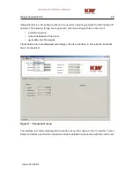
“Connection” menu
24
Figure 18:
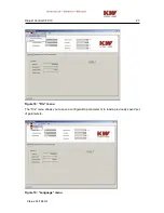
“File” menu
25
Figure 19:
“Language” menu
26
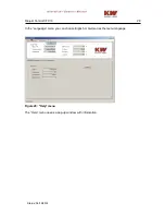
Figure 20:
“Help” menu
26
Figure 21:
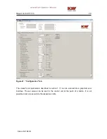
“Configuration” tab
27
Figure 22:
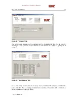
“Firmware” tab
28
Figure 23:
“Error Memory” tab
29
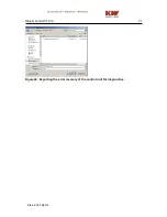
Figure 24: Exporting the error memory of the control unit for diagnostics
30


