background image

Diajekt Control CFC10 

Status: 06/18/2014 


1     Product Information 


DIAJEKT  Control  CFC10  (Chimney  Fan  Control)  is  a  control  and  regulation  unit  for  larger 

combustion  plants.  The  CFC10  controls  and  regulates  the  pressure  between  the  flue  gas 

system and the operating room. It ensures a safe operation of the fireplace. 


It can be used for all chimney fan applications, such as individual appliances, flue gas systems 

with  multiple  fireplaces,  central  heating  plants,  giant  boilers  and  industrial  systems  or  bakeries 

where a steady draught has to be ensured.  


The  Diajekt  Control  CFC10 can operate chimney fans with a  power  input of up  600W (3A). 
The  automatic  zero  balance  of  the  CFC10‟s  pressure  sensor  adds  additional  safety  and 
precision to the control. 


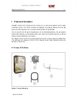
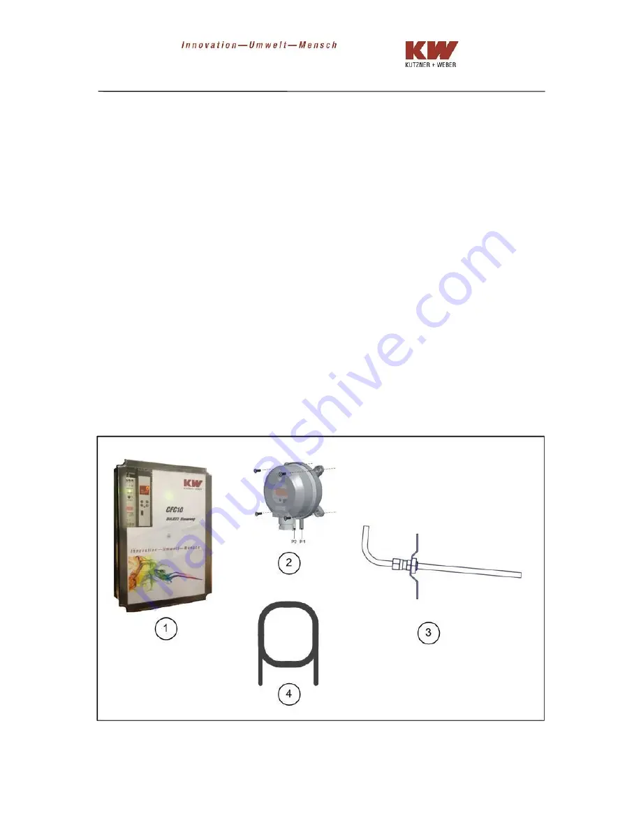
1.1 S c o p e  of Delivery 


Figure 1: Scope of Delivery


Summary of Contents for CFC10

Page 1: ...DIAJEKTControl CFC10 V2 0 Assembly Installation and Operation Instructions...

Page 2: ......

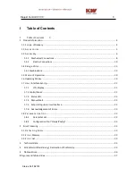
Page 3: ...ng Modes 19 1 7 User Interface Set Up 21 1 7 1 LCD Display 21 1 7 2 Control Panel 21 1 7 3 Status LED 22 1 7 4 Manual Start 23 1 7 5 Setpoint Input via User Interface 23 1 7 6 Acknowledgement of Error...

Page 4: ...of the fireplace It can be used for all chimney fan applications such as individual appliances flue gas systems with multiple fireplaces central heating plants giant boilers and industrial systems or...

Page 5: ...asuring the pressure in the flue gas system with automatic zero balance MP 3 Measuring probe for differential pressure sensor Silicone tube Length 2m 4 Supply line for pressure from measuring probe to...

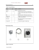
Page 6: ...antle thermocouple Type K for measuring the temperature in the flue gas system or the fireplace RSD WS 3 2002460 2 pole maintenance switch for disconnecting the control unit from power during maintena...

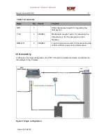
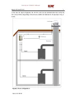
Page 7: ...18 2014 In the case of a dual configuration the CFC10 control can be installed and wired in either the first or second floor depending on structural conditions as illustrated in the example in Fig 4...

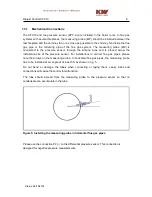
Page 8: ...the installation site of the pressure sensor For installations in vertical flue gas pipes please note the arrows on the measuring probe In horizontal flue gas pipes the measuring probe has to be inst...

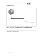
Page 9: ...Status 06 18 2014 Figure 6 Connection measuring probe and differential pressure sensor The differential pressure sensor uses the atmospheric pressure as a reference pressure level therefore it must n...

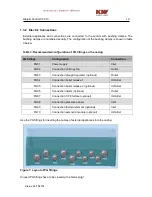
Page 10: ...Inlet PG02 Connection chimney fan Outlet PG03 Connection draught regulator optional Outlet PG04 Connection boiler release 1 In Outlet PG05 Connection boiler release 2 optional In Outlet PG06 Connecti...

Page 11: ...The CFC10 turns on the chimney fan when it receives a heating request from the boiler and immediately sends a release signal to the boiler These connections serve to detect the heating request and sen...

Page 12: ...Connection Thermal Element Type K A rise in temperature can be used as a start signal For this purpose a thermal element type K can be installed in the combustion chamber or in the flue gas system as...

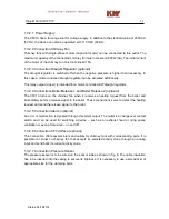
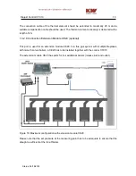
Page 13: ...0 optional This port is used for an extension module CE20 In a flue gas system with multiple fireplaces with more than two boilers a CE20 has to be installed together with the control CFC10 The extens...

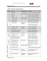
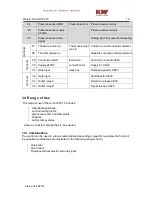
Page 14: ...e 1 N Input for release signal 1 11 Relay COM connection Output for release signal 1 12 Relay NO connection Output for release signal 1 Optional 13 Release 2 input L 24VDC or 230VAC Input for release...

Page 15: ...Supply 24VDC Supply for CE20 31 Gate input Release signal for CE20 Optional 32 Gate input Feedback for CE20 33 Outlet relay A Detection release CE20 34 Outlet relay B Signal release CE20 1 4 Range of...

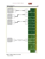
Page 16: ...Diajekt Control CFC10 16 Status 06 18 2014 1 4 1 1 One Boiler Figure 11 Wiring scheme for one boiler...

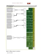
Page 17: ...Diajekt Control CFC10 17 Status 06 18 2014 1 4 1 2 Two Boilers Figure 12 Wiring scheme for two boilers...

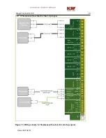
Page 18: ...Diajekt Control CFC10 18 Status 06 18 2014 1 4 1 3 Fireplace without Electric Start Up Signal Figure 13 Wiring scheme for fireplaces without electric start up signal...

Page 19: ...it is insufficient the release is canceled 1 6 Operating Modes The Diajekt Control CFC10 has the following operating modes Standby Standby of the control No heat requirements and no temperature increa...

Page 20: ...Processing During standard operation the chimney fan is turned off completely if the natural draught is sufficient In this case no chimney fan is needed A motor driven draught regulator can be activa...

Page 21: ...formation of the control The following values are displayed during standard operation device information current differential pressure current CF output current set pressure error message firmware ver...

Page 22: ...Up and Down and it is possible to start the control unit manually The reference value of the differential pressure can be changed In the case of malfunctions error messages can be acknowledged If an e...

Page 23: ...se the Up Down keys to adjust the setpoint After pressing the enter key the new value is saved and the control restarts Pressing the escape key cancels the input and the current setpoint is retained 1...

Page 24: ...time How long the chimney fan runs at maximum capacity after start up 3 999 30 s P08 CF overtravel time How long the chimney fan keeps running after a heating phase has ended 1 3600 120 s P09 Tempera...

Page 25: ...CF feedback States if a feedback signal from the chimney fan should be monitored Yes No no P21 Scaling factor Factor for the linear scaling of the differential pressure sensor 100 100 10 P22 Scaling...

Page 26: ...a USB connection correct installation of the driver up to date Net Framework Transcription errors are displayed accordingly in the user interface In this case the transcript has to be repeated Figure...

Page 27: ...Diajekt Control CFC10 27 Status 06 18 2014 Figure 18 File menu The File menu allows you to save a configuration parameter or to load a previously saved set of parameters Figure 19 Language menu...

Page 28: ...Diajekt Control CFC10 28 Status 06 18 2014 In the Language menu you can choose English or German as the menu language Figure 20 Help menu The Help menu opens a pop up window with information...

Page 29: ...onfiguration tab The values for all parameters described in section 1 7 1 can be entered into a graphical user interface The set values can be sent to the control unit at the push of a button It is no...

Page 30: ...ng an existing firmware file The firmware is transmitted to the control unit by the push of a button Figure 23 Error Memory tab All the data in the control unit s error memory can be transferred from...

Page 31: ...Diajekt Control CFC10 31 Status 06 18 2014 Figure 24 Exporting the error memory of the control unit for diagnostics...

Page 32: ...bed in section 2 3 Error Conditions 2 2 Error Memory All the error conditions described in section 3 3 are saved in a non volatile memory The error memory can be readout with the configuration tool de...

Page 33: ...eading edge Line frequency not plausible E016 Chimney fan Error timing leading edge Leading edge outlet not correct E100 24V supply too low 24V supply too low E101 24V supply too high 24V supply too h...

Page 34: ...Digital input release 1 23 VDC 230 VAC Digital input release 2 24 VDC 230 VAC Output Digital input CF feedback switch contact 24 VDC 1mA Analog outlet CF capacity motor speed 0 10V 10 mA Digital relay...

Page 35: ...verfahren Surveillance procedure Qualit tssicherungssystem QS auf Basis der DIN EN ISO 9001 2008 Wir erkl ren als Hersteller Die entsprechend gekennzeichneten Produkte erf llen die Anforderungen der a...

Page 36: ...obe DPS Differential Pressure Switch TC K Thermocouple Type K RSD WS Chimney fan Diajekt maintenance switch ST Plug CF Chimney fan ABS Acrylonitrile butadiene styrene IP International Protection USB U...

Page 37: ...mal element type K 11 Figure 10 Maximum configuration with extension module CE20 12 Figure 11 Wiring scheme for one boiler 15 Figure 12 Wiring scheme for two boilers 16 Figure 13 Wiring scheme for fir...

Page 38: ...s 06 18 2014 Table 1 Scope of Delivery 4 Table 2 Accessories 5 Table 3 Recommended configuration of PG fittings on the casing 9 Table 6 Configuration of bushing clamps 13 Table 7 Display text 21 Table...

Reviews: