background image

OPERATING INSTRUCTIONS

SPRAYER OPERATION

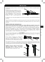
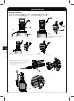
Screw the pump off the head - to do this, lock the piston rod (fig. 8b/pos. 1) in the cylinder brackets  
(fig. 8b/pos. 2). Unscrew the pump counterclockwise, holding the piston rod (fig. 8b/pos. 2).

Insert the strainer (fig. 9/pos. 2) to the head cup (fig. 9/pos. 1) and pour in the previously prepared spray liquid 
in accordance with manufacturer guidelines.

In order to secure the spraying nozzle against contamination when filling the tank with the spray liquid, it is 
recommended to rest the lance on the head (nozzle facing upwards).

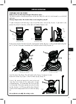
Remove the strainer (fig. 9/pos. 1) from the head cup (fig. 9/pos. 2). Screw the pump (fig. 1/pos. 5) into the 
head (fig. 1/pos. 4). To do this, lock the piston rod (fig. 8b/pos. 1) in the cylinder brackets (fig. 8b/pos. 2). 
Remember that the connection must be airtight. The locked piston rod may be used as a transport handle.

Clean any dirt off the strainer.

Move the sprayer to the work site. Use the piston rod (fig. 7a) to pump the sprayer (around 20 full motions) until 
the safety valve operates (fig. 7a/pos. 1). As soon as the safety valve opens (fig. 7a/pos. 1), maximum tank 
pressure has been reached. Monitor the tank pressure on the pressure gauge (fig. 12a/pos. 2). 

Point the lance tip (fig. 11b) at the location to be sprayed and press
 the handle lever (fig. 11b). Spraying should be performed according to main wind direction

1

Fig.10

Fig.11a

Fig.11b

The length of the sprayer lance can be 
adjusted. To do so, loosen the bell-shaped 
nut (fig. 12/pos. 2), slide out the telescopic 
section of the lance (fig. 12/pos. 1) to the 
required length (max. 0.54 m) and tighten 
the bell-shaped nut (fig. 12/pos. 2).

2

1

Fig.12

RU

EN

PL

DE

16

Summary of Contents for CLEANING PRO+ ORION SUPER Series

Page 1: ...PRO 3 0L 6 0L 9 0L 12 0L RU DE INSTRUKCJA OBS UGI BEDIENUNGSANLEITUNG OWNER MANUAL MADE IN POLAND Nr indeksu instrukcji SIO 1251 Wersja instrukcji v1 0 Data wydania 01 2018 5 lata gwarancji na zbiorni...

Page 2: ...i podstaw 9 Sitko EN 1 Telescopic lance with spraying nozzle 2 Lance handle with filter and lock 3 Hose with suction tube 4 Head 5 Pump 6 Safety valve 7 Shoulder strap 8 Pressure tank with sight glas...

Page 3: ...n Super 6 0L Orion Super 9 0L Orion Super 12 0L Wymiary d ugo x szeroko x wysoko mm Dimensions depth x width x height mm Abma e L nge x Breite x H he mm x x 210 x 250 x 500 220 x 260 x 590 230 x 280 x...

Page 4: ...J UWAGA OPRYSKIWACZ POD CI NIENIEM CHRONI PRZED UDERZENIAMI MAKSYMALNA TEMPERATURA CIECZY ROBOCZEJ NIE MO E PRZEKROCZY 30 C ZABRANIA SI ODKR CANIA G OWICY ZE ZBIORNIKA PRZEZNACZENIE Opryskiwacz ci nie...

Page 5: ...opuszczalne jest stosowanie rodk w mog cych spowodowa wybuch substancji r cych i atwopalnych 14 Prace z u yciem rodk w chemicznych w pomieszczeniach zamkni tych powinny by prowadzone w towarzystwie co...

Page 6: ...wkr ci w g owic urz dzenia rys 4b uzyskuj c szczelne po czenie Rys 4b Znajduj c si w zestawie rurk ss c rys 3 poz 1 nale y po czy z cznikiem w a rys 3 poz 2 2 Rys 4a 1 Rys 3 Sprawdzi czy w korpusie z...

Page 7: ...owicy w tym celu nale y zablokowa t oczysko rys 8b poz 1 w uchwytach cylindra rys 8b poz 2 Pomp odkr ca trzymaj c t oczysko rys 8b poz 1 w kierunku odwrotnym do kierunku ruchu wskaz wek zegara T oczy...

Page 8: ...z 1 w uchwytach cylindra rys 8b poz 2 Nale y pami ta o zachowaniu szczelno ci po czenia Zablokowane w ten spos b t oczysko mo e s u y jako uchwyt transportowy Oczy ci sitko z ewentualnych zanieczyszcz...

Page 9: ...mp rys 1 poz 5 do uzyskania szczelnego po czenia i napompowa zbiornik Na wcze niej opryskane powierzchnie wykona oprysk w celu przep ukania uk adu urz dzenia Posko czeniuspu ci ci nieniezezbiornika ry...

Page 10: ...wnienia z tytu u udzielonej gwarancji b d realizowane jedynie po przedstawieniu przez reklamu j cego wa nej karty gwarancyjnej oraz czytelnej tabliczki znamionowej znajduj cej si na zbiorniku opryskiw...

Page 11: ...Zapchana dysza rozpylaj ca na ko cu lancy rys 10 poz 1 Rozkr ci ko c wk lancy i wyj dysz rozpylaj c rys 10 poz 1 Mo na j roz o y na dwie cz ci oczy ci i z o y Spadek ci nienia w zbiorniku ci nieniowy...

Page 12: ...SURE PROTECT AGAINST IMPACT THE MAXIMUM TEMPERATURE OF SPRAY LIQUID MAY NOT EXCEED 30 C DO NOT REMOVE THE HEAD FROM THE TANK WARNING SIGNS The Orion Super pressure sprayer from the Garden Pro series i...

Page 13: ...ill into unenclosed waters 13 It is prohibited to use explosive corrosive and flammable agents 14 If working in enclosed spaces chemicals should be handled in the presence of at least two other person...

Page 14: ...to the device head fig 4b making sure that the connection is airtight Fig 4b Connect the suction tube provided fig 3 pos 1 to the hose connector fig 3 pos 2 2 Fig 4a 1 Fig 3 Make sure that the piston...

Page 15: ...do this lock the piston rod fig 8b pos 1 in the cylinder brackets fig 8b pos 2 Unscrew the pump counterclockwise holding the piston rod fig 8b pos 3 The piston rod unlocked Fig 8a The piston rod lock...

Page 16: ...the cylinder brackets fig 8b pos 2 Remember that the connection must be airtight The locked piston rod may be used as a transport handle Clean any dirt off the strainer Move the sprayer to the work si...

Page 17: ...tank Conduct some spraying onto the previously sprayed surfaces in order to rinse the device s spraying system After you finish depressurise the tank fig 1 pos 8 with the safety valve fig 7a pos 1 an...

Page 18: ...y claims will be honoured only if you have a valid warranty card and if the name plate on the sprayer tank is legible 2 The warranty is given for the period of 24 months from purchase date but no more...

Page 19: ...ng nozzle on the lance tip fig 10 pos 3 Unscrew the lance tip and remove spraying nozzle fig 10 pos 1 It can be disassembled into two pieces cleaned and reassembled Pressure drop in the tank fig 1 pos...

Page 20: ...ACHTUNG DER UNTER DRUCK STEHENDE SPR HER IST VOR SCHL GEN ZU SCH TZEN DIE MAXIMALE TEMPERATUR DES ARBEITSMEDIUMS DARF 30 C NICHT BERSCHREITEN DAS ABSCHRAUBEN DES SPR HKOPFS VOM TANK IST VERBOTEN BEST...

Page 21: ...l ssig ist der Einsatz von explosionsgef hrdeten Mitteln tzenden und leicht brennbaren Stoffen 14 Arbeiten unter Verwendung chemischer Mittel in geschlossenen R umen d rfen nur bei Anwesenheit von min...

Page 22: ...anschrauben bis eine dichte Verbindung erlangt wird Abb 4b Das im Lieferumfang enthaltene Saugrohr Abbildung 3 Position 1 ist mit dem Schlauchverbinder Abbildung 3 Position 2 zu verbinden 2 Abb 4a 1 A...

Page 23: ...g 1 Position 8 ist der Kopf des Sicherheitsventils Abbildung7a Position1 zuziehenundindieserPositionf rmindestens10Sekundenzuhalten bisdieDruckluft vollst ndig abgelassen wurde Kolbenstange nicht verr...

Page 24: ...8b Position 1 im Griff des Zylinders Abbildung 8b Position 2 blockieren Es muss an die Aufrechterhaltung der Dichtheit der Verbindung gedacht werden Die auf diese Weise blockierte Kolbenstange kann a...

Page 25: ...on 5 bis zum Erreichen einer dichten Verbindung festdrehen und Tank aufpumpen Auf zuvor bespr hte Fl chen das Wasser verspr hen um das System des Ger ts zu reinigen Nach der Beendigung mit Hilfe des S...

Page 26: ...dieser Garantie werden ausschlie lich dann realisiert wenn der Reklamierende eine g ltige Garantiekarte und ein leserliches Typenschild am Spr her vorlegt 2 Die Garantie wird f r einen Zeitraum von 2...

Page 27: ...on 1 Verstopfte Zerst uberd se am Ende der Lanze Abbildung 10 Position 1 Endst ck der Lanze aufschrauben und Zerst uberd se Abbildung 10 Position 1 herausnehmen Die D se kann in zwei Teile zerlegt wer...

Page 28: ...RU Kwazar 1 Orion Super Garden Pro 2 1 2 3 4 5 KWAZAR CORPORATION Sp z o o 30 C Orion Super Garden Pro NBR FPM Cellosolve 2 KWAZAR CORPORATION Sp z o o RU EN PL DE 28...

Page 29: ...1 2 3 4 5 1 4 1 8 6 7 8 9 10 1 1 12 13 14 15 16 17 18 19 20 21 22 23 24 5 RU EN DE PL 29...

Page 30: ...1 5 1 4 2 1 2 2 2 1 2 4 4 4 3 1 3 2 2 4a 1 3 5 2 ring 5 3 5 1 5 1 2 3 6 RU EN PL DE 30...

Page 31: ...1 8 7a 1 10 1 7a 7 7c 8 1 8 2 8 1 8a 8 2 1 2 1 9 2 9 1 9 1 9 2 7c 7a 7a 1 9 2 1 RU EN DE PL 31...

Page 32: ...8 1 8 2 8 1 9 2 9 1 9 1 9 2 1 5 1 4 8 1 8 2 7 20 7 1 7 1 12a 2 10 1 1b 1 10 1 1a 1 1 12 2 12 1 0 54 12 2 2 1 12 RU EN PL DE 32...

Page 33: ...13 1 13 2 13 1 13 1 1 8 7 1 1 5 1 8 0 25 1 5 1 8 7 1 1 5 5 35 1 5 1 4 14 1 14 10 3 1 1 13 1 2 14 1 2 RU EN DE PL Fig 15a Fig 15 1 2 3 1 2 33...

Page 34: ...KWAZAR CORPORATION Sp z o o 1 2 3 4 1 2 24 36 3 12 24 4 36 60 5 14 6 7 8 KWAZAR CORPORATION Sp z o o 9 10 1 1 RU EN PL DE 34...

Page 35: ...1 2 3 KWAZAR www kwazar com pl www kwazar com pl www sklep kwazar com pl KWAZAR CORPORATION Sp z o o 1 1 13 1 13 2 13 2 13 1 10 1 10 1 10 1 10 1 10 1 1 8 1 5 14 3 1 6 1 5 1 8 14 2 1 5 1 6 1 5 14 2 1...

Page 36: ...seller Ort des Kaufs Stempel und Unterschrift des Verk ufers Data zg oszenia i opis reklamacji Complaint date and description Datum der Meldung und Beschreibung der Reklamation Producent KWAZAR CORPOR...

Reviews: