33
SECTION: 22
COMBO CONVERSION INSTRUCTIONS
•
The process to change from the 5” gutter profile to the 6” gutter profile and then back again is considerably simplified by
using retractable pins with two secured positions that provide an easy change.
•
A tool kit is provided with every combo machine and is located inside the left-side cover at the exit end of the machine.
•
When converting from one profile to the other, it is important to follow the instructions in the correct order for efficiency.
•
The order to convert 5” to 6” is
NOT
the same as for 6” to 5”, so follow the instructions carefully.
5” to 6” CONVERSION
CAUTION:
Make sure that the machine has been disconnected from the power source before starting conversion.
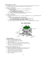
STEP 1: REMOVE ALUMINUM COVERS #1-4.
(SEE PG. 34 for lid details and for tool kit location).
•
To remove aluminum lids #1-4, use flat-head screwdriver to turn screws counter-clockwise ¼ turn.
STEP 2: REMOVE 5” GUILLOTINE AND SET ASIDE.
(SEE PG. 35 for guillotine location).
•
To remove guillotine, unscrew the four mounting bolts (E). (SEE SECTION 15, PG. 22-23).
STEP 3: MOVE BEAD ASSEMBLY TO 6” POSITION.
(SEE PG. 37)
•
Loosen the two locking bolts.
•
Slide the bead assembly up for the 6” position. (positions are marked)
•
Tighten the locking bolts.
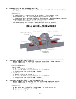
STEP 4: REMOVE BACK BELL ROLLER AND SET ASIDE.
(SEE 37)
•
To remove back bell roller, unscrew the back bell wheel bolt (W) that holds the center shaft in place.
STEP 5: MOVE BACK GUIDE BAR TO 6” POSITION.
(SEE PG. 35)
•
Loosen the five bolts on the back guide bar.
•
Move it as far away from the skate as possible.
•
Tighten the five bolts.
STEP 6: FLIP TOP #3 DRIVE BACKSIDE ROLLER.
(SEE PG. 37)
•
To flip the top #3 drive backside roller, remove the RED station (B) ¼ -20 x ½” flush head cap screws located in
the center of the roller.
•
Turn the roller end-for-end and replace it back onto the shaft by aligning the threaded holes in the shaft with the
clearance holes on the exit upper #3 top roller backside.
•
Failure to align the roller properly will cause damage
.
STEP 7: INSTALL THE BACK BELL ROLLER.
(SEE PG. 37)
•
Install the back bell roller in the 6” position labeled. (positions are marked)
STEP 8: INSTALL 6” GUILLOTINE.
(SEE PG. 23-24)
•
Remove the 6” guillotine from the side of the machine. (SEE PG. 35)
•
Install it onto the frame, using the mounting bolts removed in step 1.
•
The guillotine is factory preset and should not need adjustment.
STEP 9: STORE 5” GUILLOTINE.
(SEE PG. 35)
•
Store the 5” guillotine on the side of the machine.
STEP 10: MOVE THE 13 SKATE ROLLERS ON THE FOUR CENTER SKATES.
(SEE PG. 36)
•
To change, pull the retractable pin up at each skate until the pin disengages from the adjustable skate shaft.
•
Slide the forming roller to the 6” position and release pin.
•
Repeat this process for all thirteen rear skate-forming rollers.

