background image

Chapter 1  -  Notes on use and Safety 


232 - V 3.11.4 


Chapter 1 

Notes on use and safety  


Notes and warnings in line with DIN 57 411 Part 1a/VDE 0411 Part 1a


1.1 

Notes on use 


Mechanical effects on/interference with the display must be avoided, otherwise it could be 
destroyed. The manufacturer assumes no warranty in the event of destruction resulting from such 
mechanical effects/interference. 


You must also ensure that no extraneous voltages are applied to the test socket of the instrument, 
since this could destroy the input circuitry. 


If different cables are repeatedly connected to the test socket, the tolerances of the connectors may 
lead to fatigue of the contact springs in the test socket. You are consequently advised to insert a 
wearing part in front of the socket to avoid this. 

1.2 Safety 


The instrument is constructed and tested according to DIN 57 411 Part 1/VDE 0411 Part 1, 
protective measures for electronic measuring instruments, and left the plant in a state 
ensuring absolute safety. To maintain this and ensure its operation without posing any 
danger, the user must observe the instructions and warnings contained in this operator 
manual. 

 
Before adjustment, maintenance, repair or replacement of parts requiring the instrument to be 
opened, you must disconnect it from all voltage sources. 
Should adjustment, maintenance or repair of the opened instrument subsequently require 
application of voltage, this may only be performed by a 

specialist

 who is aware of the risks 

involved. 
Capacitors in the instrument may still be charged, even when the instrument has been 
disconnected from all voltage sources. 
 
Only use original components as replacements for safety components during repair. 
 
If it may be assumed that operation without risk or danger is no longer possible, you must shut the 
instrument down and contact the engineering after-sales service. 


Operation posing risk or danger may be assumed if 


-


the instrument exhibits visible damage, 

-


the instrument no longer functions correctly, 

-


the instrument has been stored for some time in adverse conditions, 

-


the instrument has suffered severe damage during transportation. 


The instrument is to be examined for operational safety at regular intervals. 
VBG 4, for example, stipulates such an examination every six months for instruments not 
operated in a stationary role. 

Summary of Contents for IRM 232

Page 1: ...hapter 1 Notes on use and safety 2 1 1 Notes on use 2 1 2 Safety 2 Chapter 2 Technical data 3 Chapter 3 Startup 4 3 1 Technical description 4 3 1 1 Basics of pulse reflectometry 4 3 1 2 Measuring principle 4 3 2 Operation 5 Appendix Cable types 8 ...

Page 2: ... danger the user must observe the instructions and warnings contained in this operator manual Before adjustment maintenance repair or replacement of parts requiring the instrument to be opened you must disconnect it from all voltage sources Should adjustment maintenance or repair of the opened instrument subsequently require application of voltage this may only be performed by a specialist who is ...

Page 3: ...s Dynamic range 44dB vertically in amplitude Sensitivity 70dB Digital filter Can be activated to suppress interference of external voltage on the cable Impedance 75Ohm Measurement connector IEC socket 75Ohm Measurement pulse output 4 Volt needle pulse of 5ns 20ns or 100ns pulse width POWER SUPPLY Power supply NIMH 6V 700mAh or power supply 12 to 24 Vdc or Vac Current drain 80mA Operation max 8 h C...

Page 4: ...dar system in which the transmitted signal represents a very fast jump function and the reflecting signal can be observed on its display The faster the rise of the measurement pulse the better is the resolution time equals distance The amplitude is in direct relation to the impedance meaning that measurement of matching is possible The pulse reflectometer method is thus suitable for measuring all ...

Page 5: ...ement range is automatic when the cursor crosses a band limit SELECTING VARIOUS SETTINGS LENGTH RANGE RESOLUTION OUTPUT PULSE WIDTH DIGITAL FILTER MEMORY LOCATION SHORTENING FACTOR Press and hold key 3 0 5 seconds until the symbol required is highlighted Press keys 1 and 2 to change the value selected Press keys 1 and 3 simultaneously to permanently save the width of the output pulse and the short...

Page 6: ...sor is placed at the impulse start Storage of this with pressing key 1 and 3 at the same time Back to initial state with key 3 SAVING THE SETTINGS Press keys 1 and 3 simultaneously to save the settings preselected in the display They are then available when the instrument is switched on LOW BATTERY WARNING AND SHUTDOWN If the battery voltage drops to 5 9 V the voltage is shown flashing at the top ...

Page 7: ...rmined from the pulse echos If a wide output pulse is used for measurement the pulse echos are more pronounced Defective branches and splitters then produce stronger pulse echos SHORTENING FACTOR Coaxial cable with PE dielektric 0 66 Coaxial cable with foam PE 0 82 0 78 0 95 Stripline with foam insulation 0 83 Coaxial cable with air insulation 0 9 0 88 0 92 Electric cable 0 49 0 57 ca 0 53 Attenti...

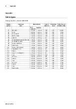
Page 8: ...7 75100 AKZ 3 5 RG6 1 00 mm 4 60 mm CPE 0 85 4 4 dB P8 LCD 95 DIGITAL 94 1 13 mm 4 80 mm CPE 0 85 4 3 dB P9 COAX 6 LG 1 70 mm 6 95 mm CPE 0 89 2 3 dB P10 LCM 14 MK 15 KOKA 7 1 63 mm 7 20 mm CPE 0 84 2 8 dB P11 TELASS B1 1 7 3 1 10 mm 7 25 mm PE 0 66 3 8 dB P12 PRG 11 1 55 mm 7 25 mm CPE 0 81 2 7 dB P13 1 ikx 1 1 7 3 KOKA 741 1 10 mm 7 30 mm PE 0 66 3 3 dB P14 1 nkx 2 20 mm 8 80 mm PEH 0 88 1 8 dB ...

Reviews: