background image

4


Chapter 3  -  Startup


232 - V 3.11.4 

Chapter 3 

Startup 

3.1 Technical 

description


The instrument is a lightweight, compact, microprocessorized unit with an LCD display for 
troubleshooting and inspecting TV/SAT cable installations, communication and power lines. 

3.1.1  Basics of pulse reflectometry  

Pulse reflectometry (time domain reflectometer) is a modern application of tried and tested pulse 
reflection measurement technology, which for many years already has proved to be a valuable aid 
for troubleshooting transmission lines. It allows precise and reliable pinpointing of cable or line 
damage. 
 
A pulse is continuously applied to the line being measured. If this pulse encounters a malfunction 
(eg shortcircuit) or an interruption, it is reflected back to its point of origin. There it is compared in 
phase, time and amplitude with the original pulse. The comparison of propagation time shows the 
distance to the point of defect and also indicates the nature of the defect. 
 
With a better generator for producing extremely short pulses and a signal receiver with large 
bandwidths, it is also possible to conduct measurements of all RF cables. The sampling technique 
allows measurements from several hundred meters down to a few centimeters plus accurate 
measurement of reflection and amplitude of the order of a few millivolts. 
 
The pulse reflectometer is consequently a kind of enclosed, unidimensional radar system in which 
the transmitted signal represents a very fast jump function and the reflecting signal can be 
observed on its display. The faster the rise of the measurement pulse, the better is the resolution 
(time equals distance). 
 
The amplitude is in direct relation to the impedance, meaning that measurement of matching is 
possible. The pulse reflectometer method is thus suitable for measuring all cables, connectors, 
transformers, matching elements, striplines, broadband transformers. directional couplers and 
cable attenuations. 

3.1.2 Measuring principle 

The instrument works in the time domain. It is to be thought of as an enclosed radar system. 
The measurement pulses fed into the cable are reflected by the inhomogeneities of the cable 
impedance (cable defects) and shown on the display. 
 
From the shape and the time offset of the reflection it is possible to determine the nature of the 
defect and the distance to the defect. 
The shortening factor (or pulse speed) indicates how fast electrical signals propagate in a cable in 
relation to the speed of light. The highest speed of propagation is achieved in the air with a 
shortening factor of 1.00. 
 
The shortening factor of the cable being investigated must be set before commencing to measure 
the length. If the factor is unknown, set an approximate value and determine the defect from both 
ends of the cable. 
 
In order to determine an unknown shortening factor (SF) value precisely, cut the cable to exactly 10 
metres with a tape measure, and change the SF on the measuring instrument during the 
measurement process until it shows exactly 10 metres. 


Summary of Contents for IRM 232

Page 1: ...hapter 1 Notes on use and safety 2 1 1 Notes on use 2 1 2 Safety 2 Chapter 2 Technical data 3 Chapter 3 Startup 4 3 1 Technical description 4 3 1 1 Basics of pulse reflectometry 4 3 1 2 Measuring principle 4 3 2 Operation 5 Appendix Cable types 8 ...

Page 2: ... danger the user must observe the instructions and warnings contained in this operator manual Before adjustment maintenance repair or replacement of parts requiring the instrument to be opened you must disconnect it from all voltage sources Should adjustment maintenance or repair of the opened instrument subsequently require application of voltage this may only be performed by a specialist who is ...

Page 3: ...s Dynamic range 44dB vertically in amplitude Sensitivity 70dB Digital filter Can be activated to suppress interference of external voltage on the cable Impedance 75Ohm Measurement connector IEC socket 75Ohm Measurement pulse output 4 Volt needle pulse of 5ns 20ns or 100ns pulse width POWER SUPPLY Power supply NIMH 6V 700mAh or power supply 12 to 24 Vdc or Vac Current drain 80mA Operation max 8 h C...

Page 4: ...dar system in which the transmitted signal represents a very fast jump function and the reflecting signal can be observed on its display The faster the rise of the measurement pulse the better is the resolution time equals distance The amplitude is in direct relation to the impedance meaning that measurement of matching is possible The pulse reflectometer method is thus suitable for measuring all ...

Page 5: ...ement range is automatic when the cursor crosses a band limit SELECTING VARIOUS SETTINGS LENGTH RANGE RESOLUTION OUTPUT PULSE WIDTH DIGITAL FILTER MEMORY LOCATION SHORTENING FACTOR Press and hold key 3 0 5 seconds until the symbol required is highlighted Press keys 1 and 2 to change the value selected Press keys 1 and 3 simultaneously to permanently save the width of the output pulse and the short...

Page 6: ...sor is placed at the impulse start Storage of this with pressing key 1 and 3 at the same time Back to initial state with key 3 SAVING THE SETTINGS Press keys 1 and 3 simultaneously to save the settings preselected in the display They are then available when the instrument is switched on LOW BATTERY WARNING AND SHUTDOWN If the battery voltage drops to 5 9 V the voltage is shown flashing at the top ...

Page 7: ...rmined from the pulse echos If a wide output pulse is used for measurement the pulse echos are more pronounced Defective branches and splitters then produce stronger pulse echos SHORTENING FACTOR Coaxial cable with PE dielektric 0 66 Coaxial cable with foam PE 0 82 0 78 0 95 Stripline with foam insulation 0 83 Coaxial cable with air insulation 0 9 0 88 0 92 Electric cable 0 49 0 57 ca 0 53 Attenti...

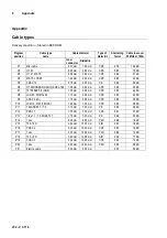
Page 8: ...7 75100 AKZ 3 5 RG6 1 00 mm 4 60 mm CPE 0 85 4 4 dB P8 LCD 95 DIGITAL 94 1 13 mm 4 80 mm CPE 0 85 4 3 dB P9 COAX 6 LG 1 70 mm 6 95 mm CPE 0 89 2 3 dB P10 LCM 14 MK 15 KOKA 7 1 63 mm 7 20 mm CPE 0 84 2 8 dB P11 TELASS B1 1 7 3 1 10 mm 7 25 mm PE 0 66 3 8 dB P12 PRG 11 1 55 mm 7 25 mm CPE 0 81 2 7 dB P13 1 ikx 1 1 7 3 KOKA 741 1 10 mm 7 30 mm PE 0 66 3 3 dB P14 1 nkx 2 20 mm 8 80 mm PEH 0 88 1 8 dB ...

Reviews: