Chapter 15 - Spectrum analyzer 113
106 V3.2
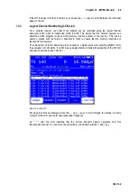
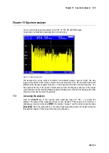
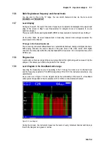
The level differential between the two cursor positions is also displayed in the 1
st
line to the right “2-
1” stands for the difference between the right (2
nd
) and left (1
st
) cursor.
No level reduction is taken into account in the level displays. This means that these are the
absolute levels. The level differential which appears in the brackets does, however, include the
level reduction. This means that these displays can be used to set the reference line between the
cursors exactly horizontal.
This function is activated via the
TILT
menu item. You can end the tilt measurement by selecting
the
BACK
menu item.
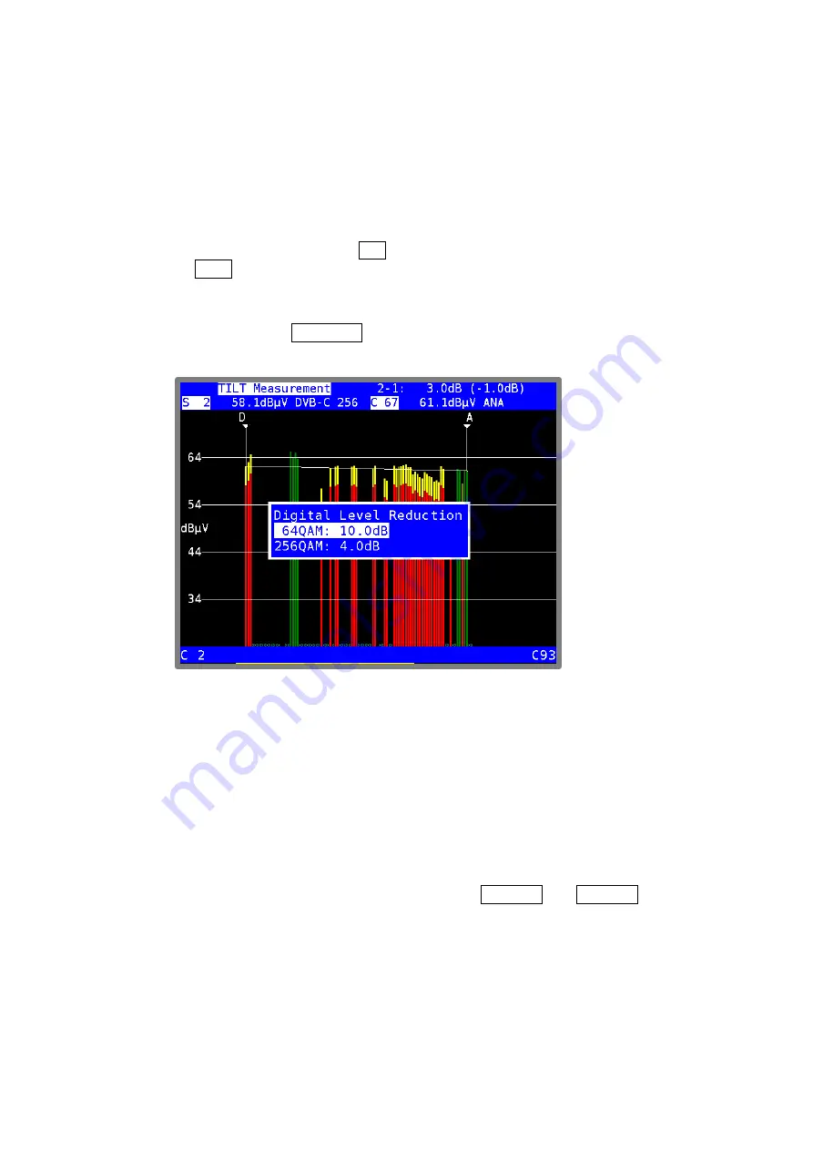
Digital level reduction
15.10.1
Using the menu item
LEVEL RED
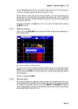
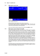
, the level reduction for digital channels can be set depending on
the modulation scheme.
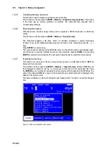
Figure 15-5 TILT measurement - digital level reduction
You can use the
↑/↓
keys to select the desired entry field and open the input mask by pressing
ENTER
. You can now change the value using the numeric keypad or the arrow keys. Confirm
every entry using the
ENTER
key. The cursor then jumps to the next field and the value entered is
permanently saved.
Exit this menu by selecting
HOME
.
Selecting a profile
15.10.2
The measuring instrument can manage two different profiles per FULLSPAN and FULL EXT mode
for the tilt measurement. The profiles save the channels which are to be used for the measurement.
The profiles can be selected using the menu items
PROFILE1
and
PROFILE2
. Thereby the
profiles correspond to the active span, so the PROFILE1 of the FULLSPAN mode contains different
data as the PROFILE1 of FULL EXT mode.

