Chapter 24 - Wi-Fi™ 147
106 V3.2
24.5
Measurement Capabilities
Channel allocation
24.5.1
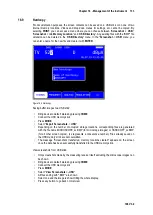
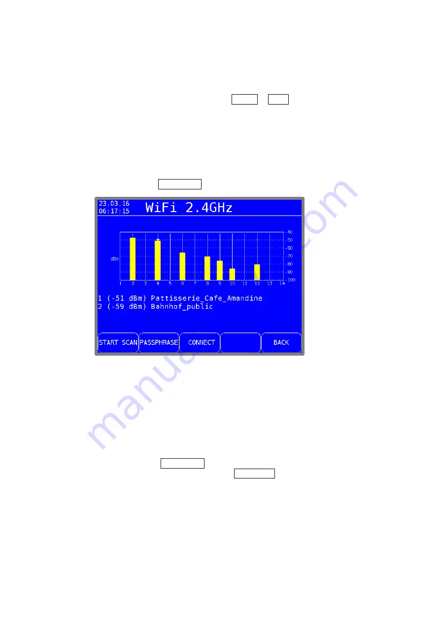
The cannel assignment of all access points found in the area are plotted on a graph (Figure 24-1
Wi-Fi™ channel diagram). The function keys
2.4 GHz
or
5 GHz
you can call the diagram for the
2.4 GHz band (802.11 b/g/n) or 5 GHz band (802.11a).
Depending of the band (2.4 GHz or 5 GHz) varies the number of possible channels. Each access
point is transmitting on a particular channel. The bar height corresponds to the reception level in
dBm (from -40 dBm to -96 dBm).
When multiple access points sending on the same channel, only the beam of the best received
access point will be shown. Below the chart will display up to four access points (which are best
received) transmitting on the channel. Use the cursor keys to switch between the individual
channels.
With the function key
START SCAN
a renewed single scan started for new access points.
Figure 24-1 Wi-Fi™ channel diagram
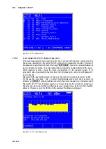
Overview of all access points in the area
24.5.2
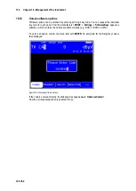
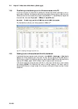
In the main menu, all access points found are displayed with their respective level, channel and
encryption. The order is sorted by the reception level strength. With the channel number on which
the access point sends can the frequency band detected: Channels y 15 are in the 2.4 GHz band,
channels > 35 are in the 5 GHz band. From this view, a level measurement can be started. Using
the cursor keys
↑
and
↓
to select the corresponding access point.
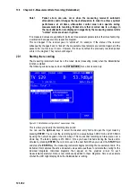
Continuous scan mode:
With the function key
START SCAN
a continuous scan can be activated. To stop the continuous
scan operation press the same function key (
STOP SCAN
). Stopping the scan may take a few
seconds until the last scan is completely finished.

